
DreamCatcher AM3
This is one of two "re-builds" I'm working on as well as a "new" build...... 
This work log is for what I hope is THE final version of said named computer build as it has gone to a total AM3 package. My systems have always been give names and I tend to consistently revise them. That is why there are revision numbers. Of course those of you that have dealt with me know this!
Brief background as this will be the 4th (5th??) worklog for DreamCatcher. Originally this unit started March, ’07 and was housed in an Ultra MicroFly, then “re-clothed†as a MX6, with its final migration into a Silverstone SG01 Evolution. Processor wise it has gone through 939 with Opteron 165, 170, and I believe a 185. Then for AM2 – AM2+ it has seen a Brisbane 4000+, Opteron 1210, PI X2 7750BE, and PI X2 8750BE. Then AM3 with PII X3 720BE, PII X4 945, and finally this build which has the 955BE. All because of “updating†other builds.
For those that have the time and inclination here are some links for its prior versions:
DreamCatcher
DreamCatcher v2.0 “Worklogâ€
DreamCatcher v3.0
DreamCatcher v3.5
DreamCatcher is Now v3.5 Worklog - The Last Version!
As the “engineering†for most of this build occurred prior I’ll try to show that in some sense of order……………..
Specs for the system are as follows:
Mobo: MSI 785GM-E65
CPU: PII X4 955 w/ Cuplex XT di
PSU: MODU82+ EMD525AWT
GPU: XFX GTX 285 w/ EK-FC285 GTX Block
HDD: Seagate 7200.10 ST380815AS 80GB
Memory: F3-12800CL7D-2GBPI (may get a second set for 4 x 1GB)
OS: M$ XP Pro SP3 (Looking to go Win7 soon)
Right now I only have two set of DDR3 memory to share between two builds, but what the hey……XP doesn’t see all of the 4GB anyway! Originally this was to be my primary folder and file server. However with the installation of first a WC’ed BFG GTX 280 and now the 285 the SG01’s HDD drive cage had to go by – by. Also while showing the “physicals mods†you may see some of the older components. Had thought to show a timeline but dropped the idea. Initially am just going to show what was done that is still applicable until we get to the current work.
IN THE BEGINNING…………
As with all of my builds in the past, when new hardware is acquired the old kinda sorta flows down hill – “know what I mean Vern?†Sometime late in its Ultra MX6 version I decided I wanted to try water cooling. However being a noob to that and knowing it was to be done as a mATX system I decided to take the easy way out and use a self contained system. SO the parts that have been the same up to and including this version are from Aqua Computer. The self-contained rad/res/pump is the Aquaduct 240 PRO Mark II. It seemed to be a functional choice and a nice piece of “furniture†to boot. Also the CPU cooler that has hung around from the beginning is the Cuplex XT di
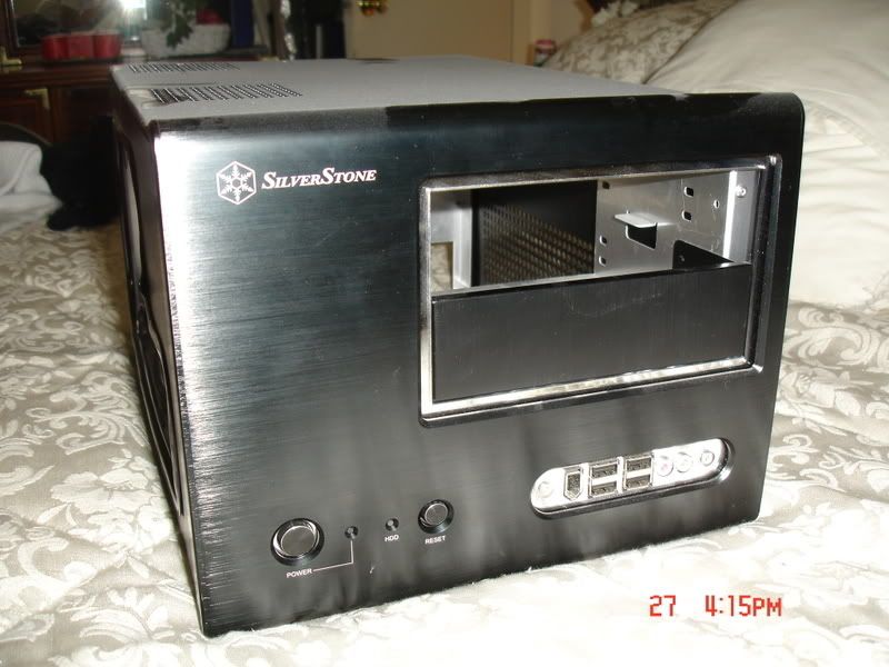
As the fates would have it several mobo changes occurred and when trying to figure out what to do with some other components a decision was made! It had been decided that I was going to move all of DC’s stuff into the SilverStone SOG1 I had hidden in attic. As you follow my builds another “standard†will appear….I tend to fall “victim†to eBay. More than one design change or upgrade has because of this. Hence the SG01 hidden from the boss in the attic.
The case’s prior owner cut a window in the side and apparently had a rad screwed to the top. These are his pictures……… and yes the dust was free!
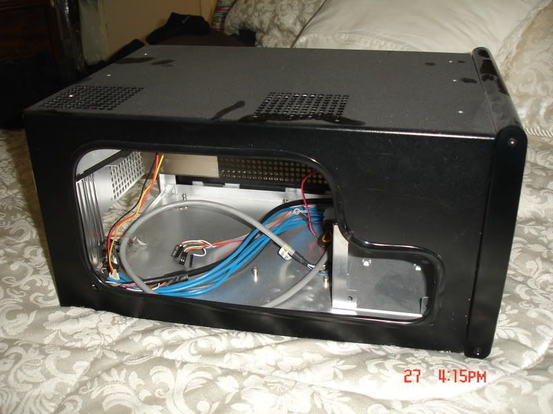
Edging had been used to cover the cut, but it one was to attach a piece of plex for a window with that in place it would not have fit. Something the prior owner must not have taken in to consideration when doing the window was how close the cover is to the frame when mounted. After working with this I then understood why the factory windowed cover has the window mounted on the outside!
So I removed the edging and found a pretty good edge for the cutout. Where it was “rough†is in the bottom corners where the cooling holes are located. As you can see here ……….
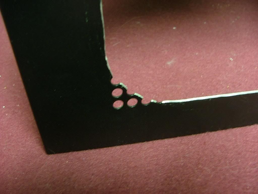
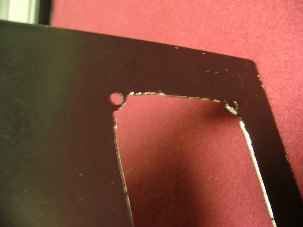
It was decided to “square†the corners as best I could and file the “rough†areas to be the finished edge and attach the window behind. This required some resizing and a fair amount of “hammer, grind, and file to suitâ€â€¦..so much so that I still haven’t declared this part completed.
 [BMG]http://i34.photobucket.com/albums/d140/jedihobbit/DreamCatcherv3/SOG1CornerRedo3.jpg[/BMG]
I hoped when I patched the six taped holes on top………
Did a final sanding, and painted the window edges will “clean upâ€. Now on to the window.
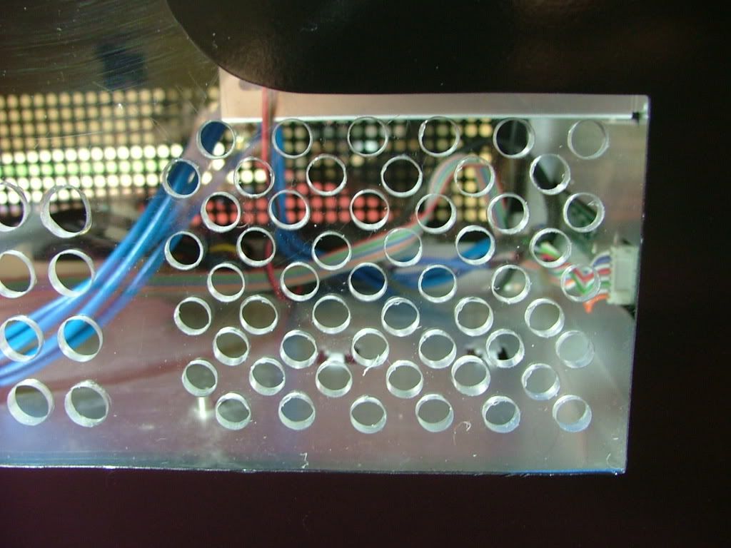
Had a spare piece of plex lying around so decided to do an “engineering sample†of the window. The biggest thing in putting in a window is the lose of cooling hole .…. especially those required by the hdd cage fan.
I taped the plex to the opposite side and scribed holes based on its hole pattern. My spacing and sizing will be different as I was afraid of cracking the plex if the holes were too close. Will have multiple small holes in the hdd area with fewer large holes (3/8â€) for the rest. Here you see the rough layout with center punches prior to drilling. The centers are “eye-balled†so it won’t be all that nice and neat (after all this is “just a testâ€)!
You may wonder why I called the window an “engineering sampleâ€, quit simple……….
By “experimenting†on hole sizes and locations I’ve saved a wee bit of heart break. As you can see the material I have on hand is too brittle to drill. What I was able to do shows me the hole spacing is fine, but the pattern associated with the HDD fan needs to be lowered. Now to find some lexan to work with.
Needing to patch the holes in the top of the cover I drug out the stuff I used when doing the side panels of my first and still unfinished build Celtic Spirit.
It is easy to use and I just hope not too old! Backed the holes using “painters’†tape so as to only need to sand one side. As it was, I didn’t mixed enough catalyst and it required a little over 2 – 2-1/2 times longer to cure. Then it was sanding time!! Also took the opportunity to smooth out as best I could the edges of the window opening.
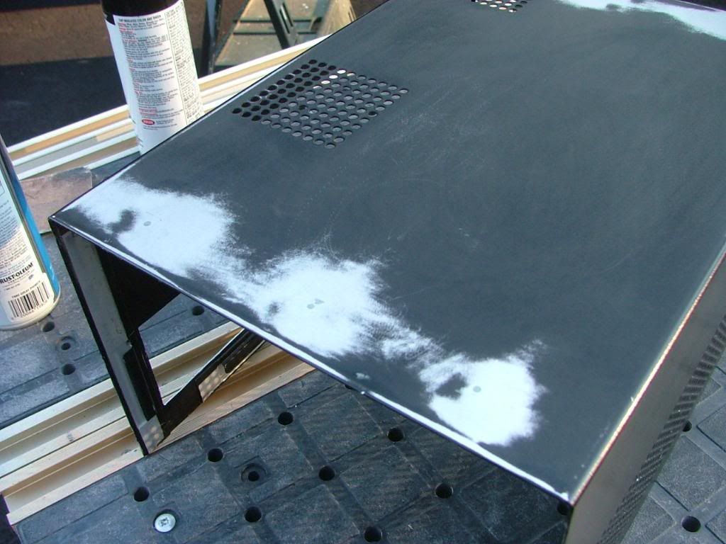
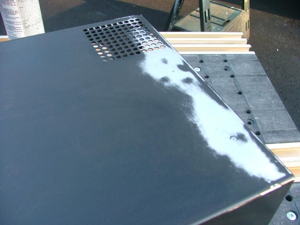
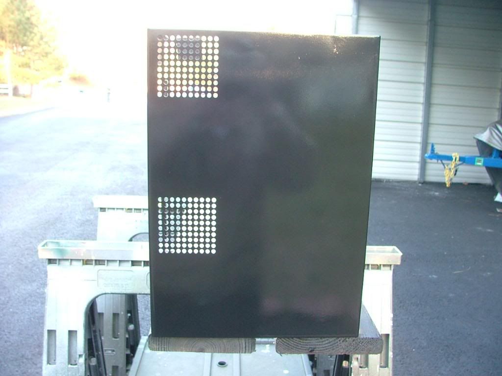
Here we are ready for the painting and after it was “done†it appeared to be fairly reflective. I jokingly referred to the method as “quick and dirty†because of doing in a few hours what should be done in a couple of days. However in the last pic you’ll see the patched holes….which if I had not skipped the primer, had sufficient coats of paint (with sanding between) they shouldn’t have been seen. Let’s just say this isn’t one of my better paint jobs and needs to be located in a “dark†area of the office!
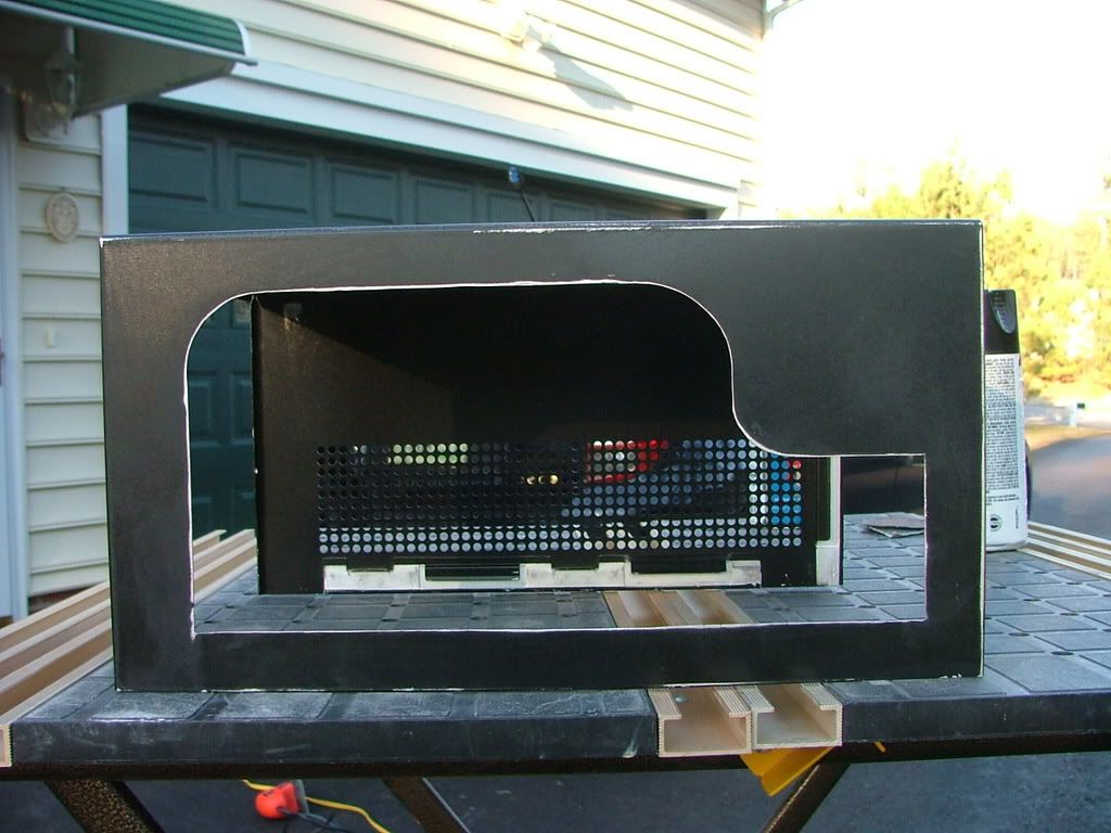

I managed to purchase a piece of Lexan for “drill ability†to use for the window. These pix were while laying out the hole patterns and beginning to drill. While it may appear somewhat inconsistent it was decided on two different size holes and patterns. You may notice the two stray holes up top……that was a “test†in an area not seen. If you look closely you’ll see where the window edge is.
Lexan makes a big difference when it comes to drilling! It was easier by far over the plex but has it own minor issues. Rule of thumb, Plex is hard but brittle where as Lexan is soft and workable. I used a wireless drill at low speeds but it would still grab on occasions. Also I had difficulty in cleaning any “rough†edges and in the process managed to scratch the surface and will need to spend the time to find and use some “glass polishâ€. The major drawback of “softâ€. Here you have it temporarily mounted and in the closer views see some of the needed clean up.
Haven’t been totally “pleased†with it and as stated earlier due to needing additional work have just sat it aside for now. Here is where I can put a plug in for Silverstone’s customer service. They have spare parts for their cases and don’t seem to hesitate to sale them either. While I’m a big fan of Ultra’s MicroFly cases one needs to be “careful†as they will not sale any replacement parts. At any rate I acquired a factory windowed cover until I’m happy with my version.
One of the things I tried to do was to make the WC loop somewhat modular as half of it is outside the case. First with the MicroFly and then with the SG01 I mounted bulkhead fittings so and then an additional set of shutoff valves outside the case. Even though the Aquaduct has its on set of valves I could still stop the flow at the rear of the case. The one thing that I really miss from the Ultra design is the mobo tray which made disassembly very easy. However with the bulkhead fittings mobo removal was all that bad. To cut to the chase and trim the BS I’ll just though out a patch of pics showing this in the past. If there are any specific questions to what is happening just ask.
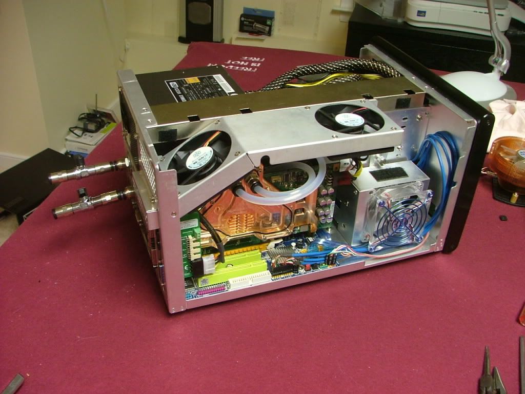
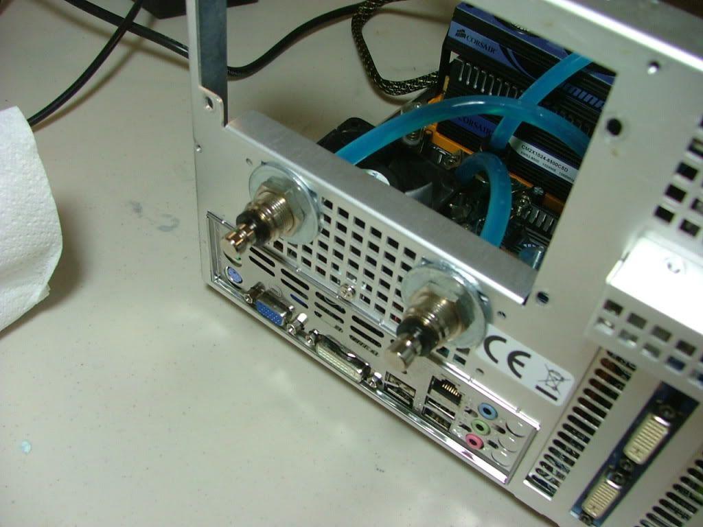
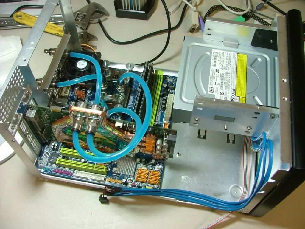
Also another nice thing about having the loop modular is it allows things like testing and overclocking somewhere other than in the case……….
And then when you're done, in it goes!
This work log is for what I hope is THE final version of said named computer build as it has gone to a total AM3 package. My systems have always been give names and I tend to consistently revise them. That is why there are revision numbers. Of course those of you that have dealt with me know this!
Brief background as this will be the 4th (5th??) worklog for DreamCatcher. Originally this unit started March, ’07 and was housed in an Ultra MicroFly, then “re-clothed†as a MX6, with its final migration into a Silverstone SG01 Evolution. Processor wise it has gone through 939 with Opteron 165, 170, and I believe a 185. Then for AM2 – AM2+ it has seen a Brisbane 4000+, Opteron 1210, PI X2 7750BE, and PI X2 8750BE. Then AM3 with PII X3 720BE, PII X4 945, and finally this build which has the 955BE. All because of “updating†other builds.
For those that have the time and inclination here are some links for its prior versions:
DreamCatcher
DreamCatcher v2.0 “Worklogâ€
DreamCatcher v3.0
DreamCatcher v3.5
DreamCatcher is Now v3.5 Worklog - The Last Version!
As the “engineering†for most of this build occurred prior I’ll try to show that in some sense of order……………..
Specs for the system are as follows:
Mobo: MSI 785GM-E65
CPU: PII X4 955 w/ Cuplex XT di
PSU: MODU82+ EMD525AWT
GPU: XFX GTX 285 w/ EK-FC285 GTX Block
HDD: Seagate 7200.10 ST380815AS 80GB
Memory: F3-12800CL7D-2GBPI (may get a second set for 4 x 1GB)
OS: M$ XP Pro SP3 (Looking to go Win7 soon)
Right now I only have two set of DDR3 memory to share between two builds, but what the hey……XP doesn’t see all of the 4GB anyway! Originally this was to be my primary folder and file server. However with the installation of first a WC’ed BFG GTX 280 and now the 285 the SG01’s HDD drive cage had to go by – by. Also while showing the “physicals mods†you may see some of the older components. Had thought to show a timeline but dropped the idea. Initially am just going to show what was done that is still applicable until we get to the current work.
IN THE BEGINNING…………
As with all of my builds in the past, when new hardware is acquired the old kinda sorta flows down hill – “know what I mean Vern?†Sometime late in its Ultra MX6 version I decided I wanted to try water cooling. However being a noob to that and knowing it was to be done as a mATX system I decided to take the easy way out and use a self contained system. SO the parts that have been the same up to and including this version are from Aqua Computer. The self-contained rad/res/pump is the Aquaduct 240 PRO Mark II. It seemed to be a functional choice and a nice piece of “furniture†to boot. Also the CPU cooler that has hung around from the beginning is the Cuplex XT di
As the fates would have it several mobo changes occurred and when trying to figure out what to do with some other components a decision was made! It had been decided that I was going to move all of DC’s stuff into the SilverStone SOG1 I had hidden in attic. As you follow my builds another “standard†will appear….I tend to fall “victim†to eBay. More than one design change or upgrade has because of this. Hence the SG01 hidden from the boss in the attic.
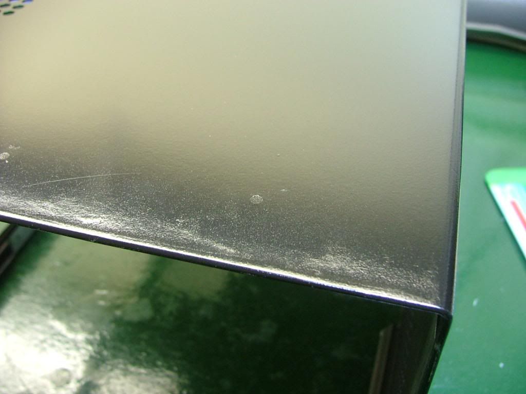
The case’s prior owner cut a window in the side and apparently had a rad screwed to the top. These are his pictures……… and yes the dust was free!
Edging had been used to cover the cut, but it one was to attach a piece of plex for a window with that in place it would not have fit. Something the prior owner must not have taken in to consideration when doing the window was how close the cover is to the frame when mounted. After working with this I then understood why the factory windowed cover has the window mounted on the outside!
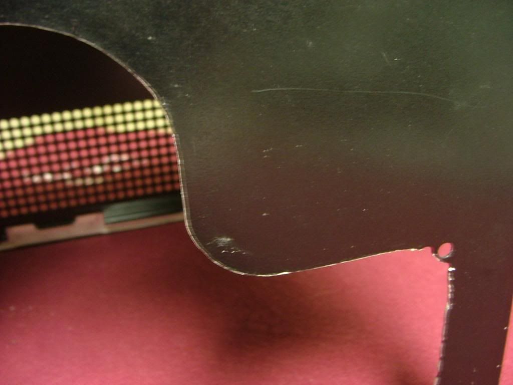
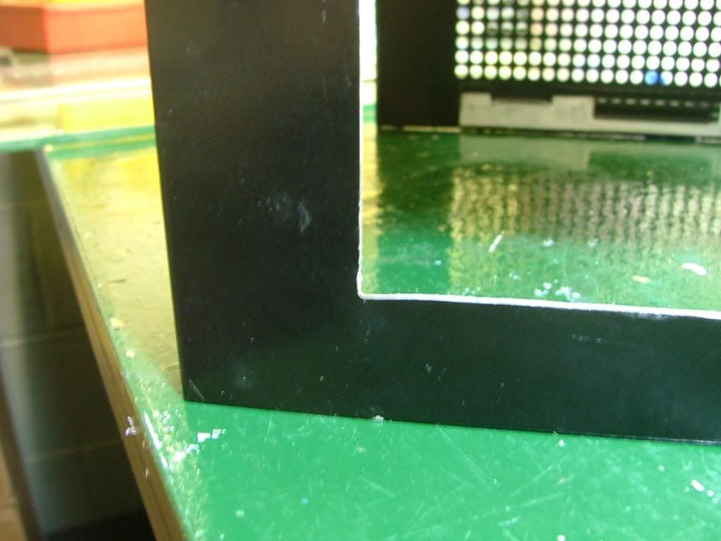
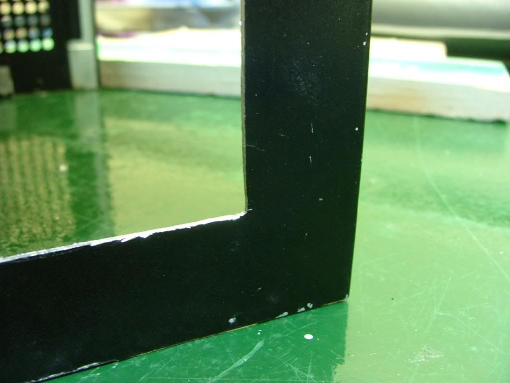
So I removed the edging and found a pretty good edge for the cutout. Where it was “rough†is in the bottom corners where the cooling holes are located. As you can see here ……….
It was decided to “square†the corners as best I could and file the “rough†areas to be the finished edge and attach the window behind. This required some resizing and a fair amount of “hammer, grind, and file to suitâ€â€¦..so much so that I still haven’t declared this part completed.
[BMG]http://i34.photobucket.com/albums/d140/jedihobbit/DreamCatcherv3/SOG1CornerRedo3.jpg[/BMG]![http://i34.photobucket.com/albums/d140/jedihobbit/DreamCatcherv3/SOG1CornerRedo3.jpg[/BMG]](http://i34.photobucket.com/albums/d140/jedihobbit/DreamCatcherv3/SOG1CornerRedo3.jpg[/BMG])
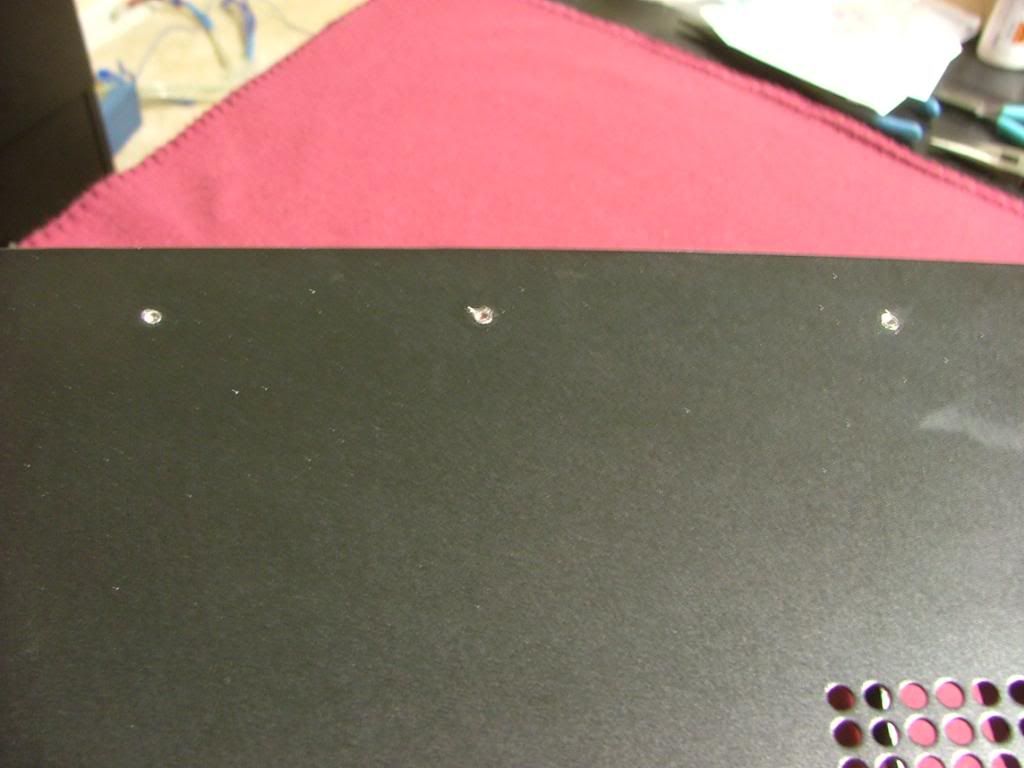
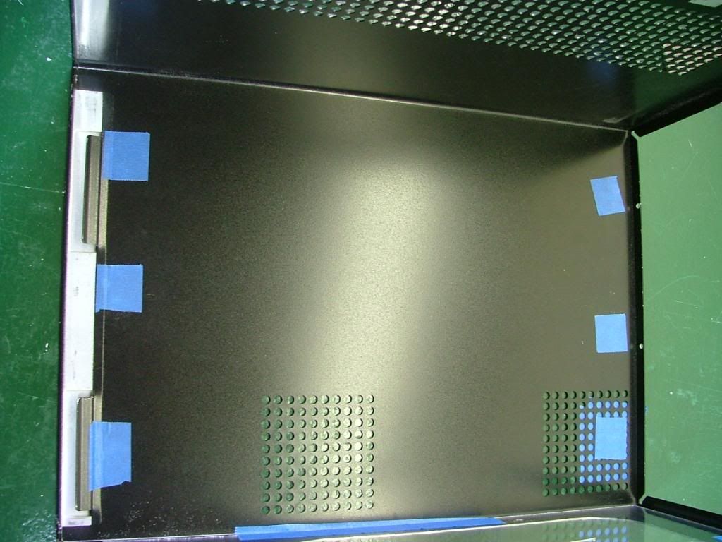
I hoped when I patched the six taped holes on top………
Did a final sanding, and painted the window edges will “clean upâ€. Now on to the window.
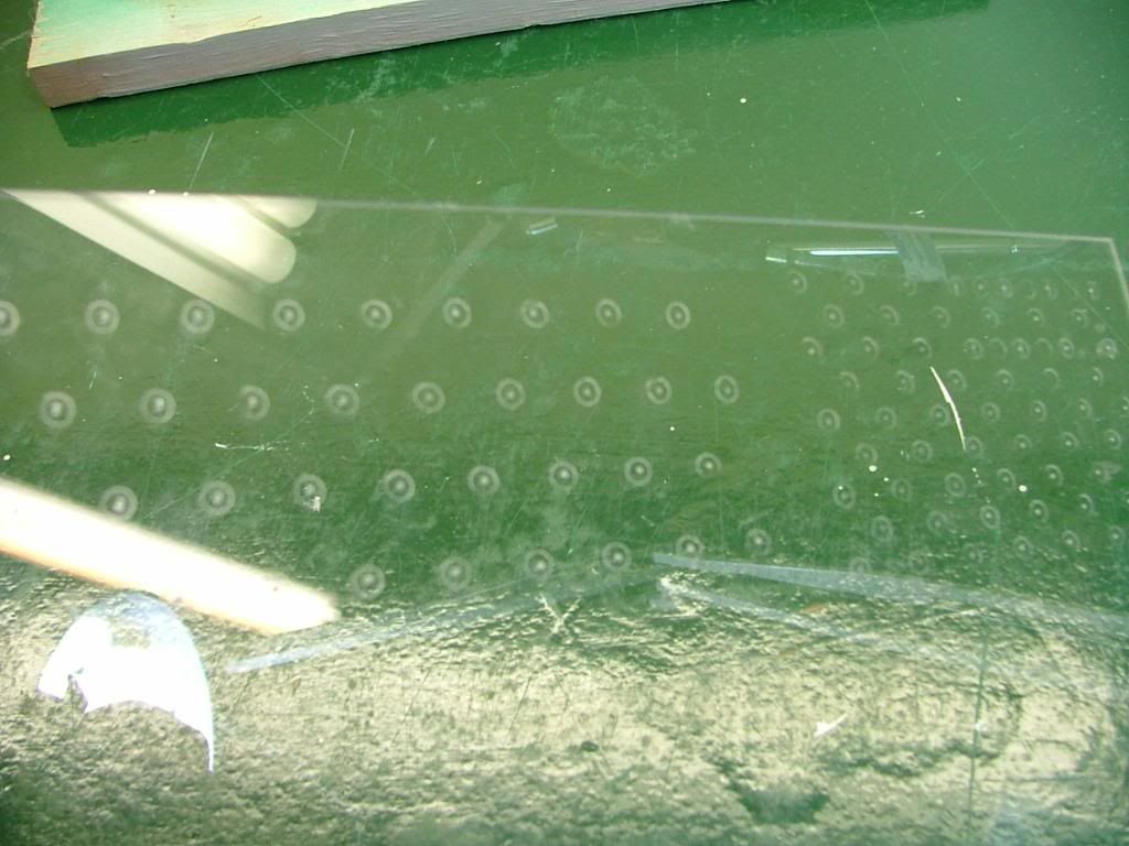
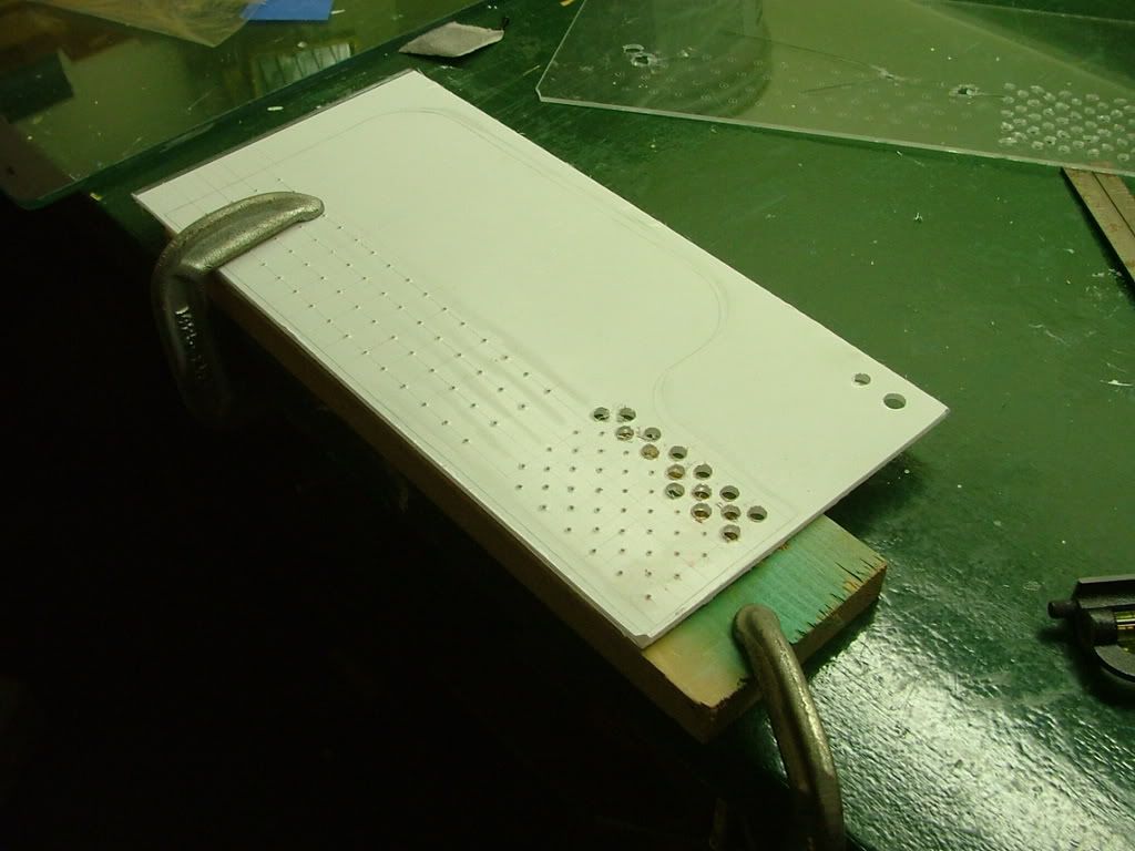
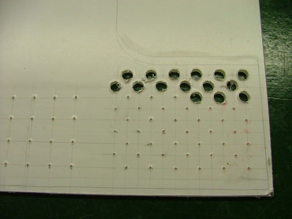
Had a spare piece of plex lying around so decided to do an “engineering sample†of the window. The biggest thing in putting in a window is the lose of cooling hole .…. especially those required by the hdd cage fan.
I taped the plex to the opposite side and scribed holes based on its hole pattern. My spacing and sizing will be different as I was afraid of cracking the plex if the holes were too close. Will have multiple small holes in the hdd area with fewer large holes (3/8â€) for the rest. Here you see the rough layout with center punches prior to drilling. The centers are “eye-balled†so it won’t be all that nice and neat (after all this is “just a testâ€)!
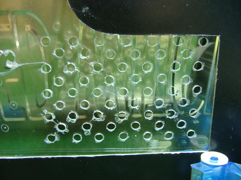
You may wonder why I called the window an “engineering sampleâ€, quit simple……….
By “experimenting†on hole sizes and locations I’ve saved a wee bit of heart break. As you can see the material I have on hand is too brittle to drill. What I was able to do shows me the hole spacing is fine, but the pattern associated with the HDD fan needs to be lowered. Now to find some lexan to work with.
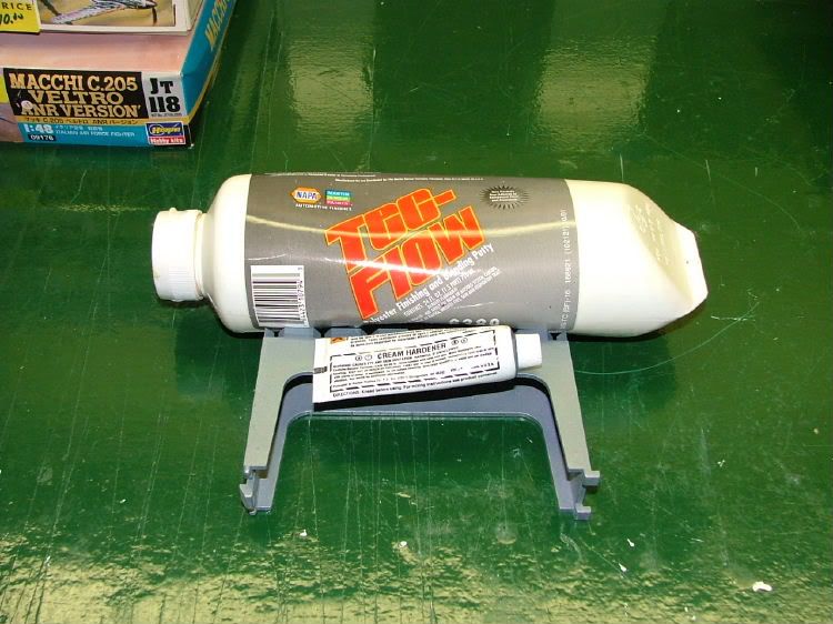
Needing to patch the holes in the top of the cover I drug out the stuff I used when doing the side panels of my first and still unfinished build Celtic Spirit.
It is easy to use and I just hope not too old! Backed the holes using “painters’†tape so as to only need to sand one side. As it was, I didn’t mixed enough catalyst and it required a little over 2 – 2-1/2 times longer to cure. Then it was sanding time!! Also took the opportunity to smooth out as best I could the edges of the window opening.
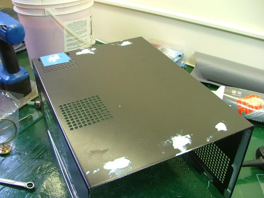
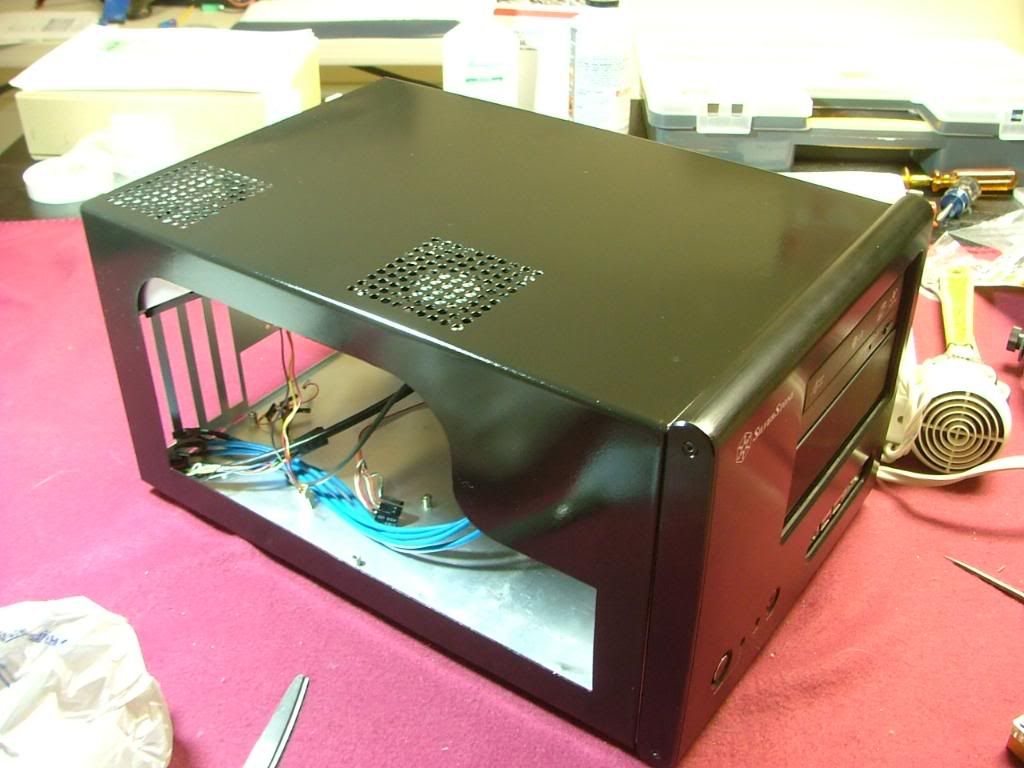
Here we are ready for the painting and after it was “done†it appeared to be fairly reflective. I jokingly referred to the method as “quick and dirty†because of doing in a few hours what should be done in a couple of days. However in the last pic you’ll see the patched holes….which if I had not skipped the primer, had sufficient coats of paint (with sanding between) they shouldn’t have been seen. Let’s just say this isn’t one of my better paint jobs and needs to be located in a “dark†area of the office!
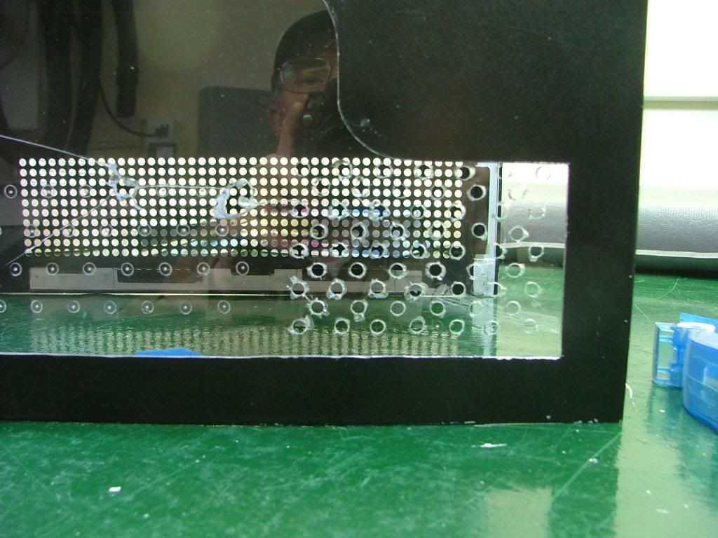
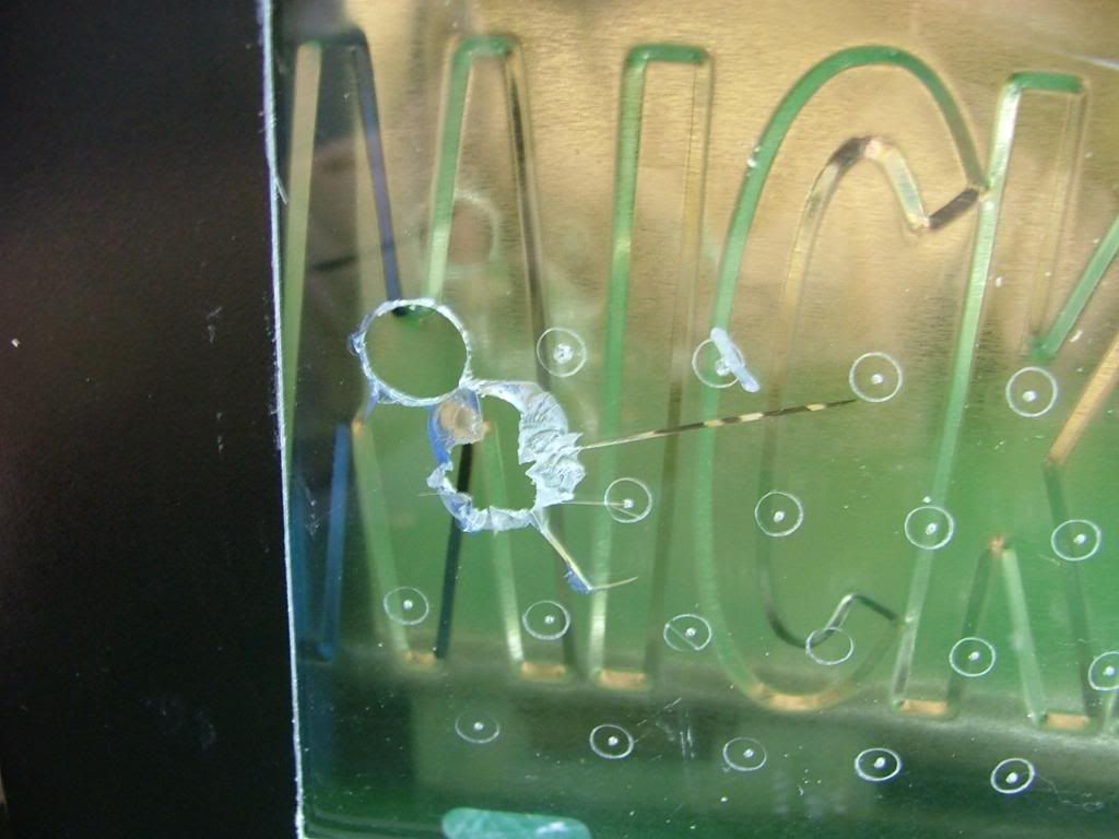
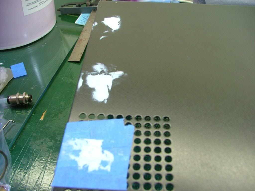
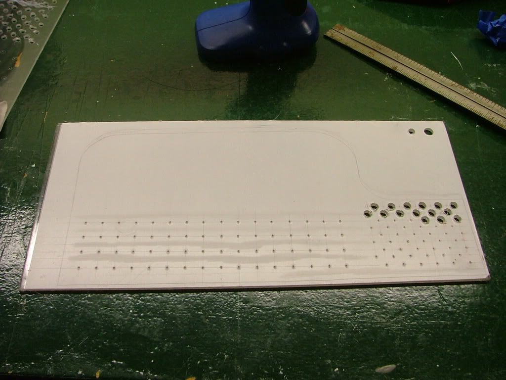
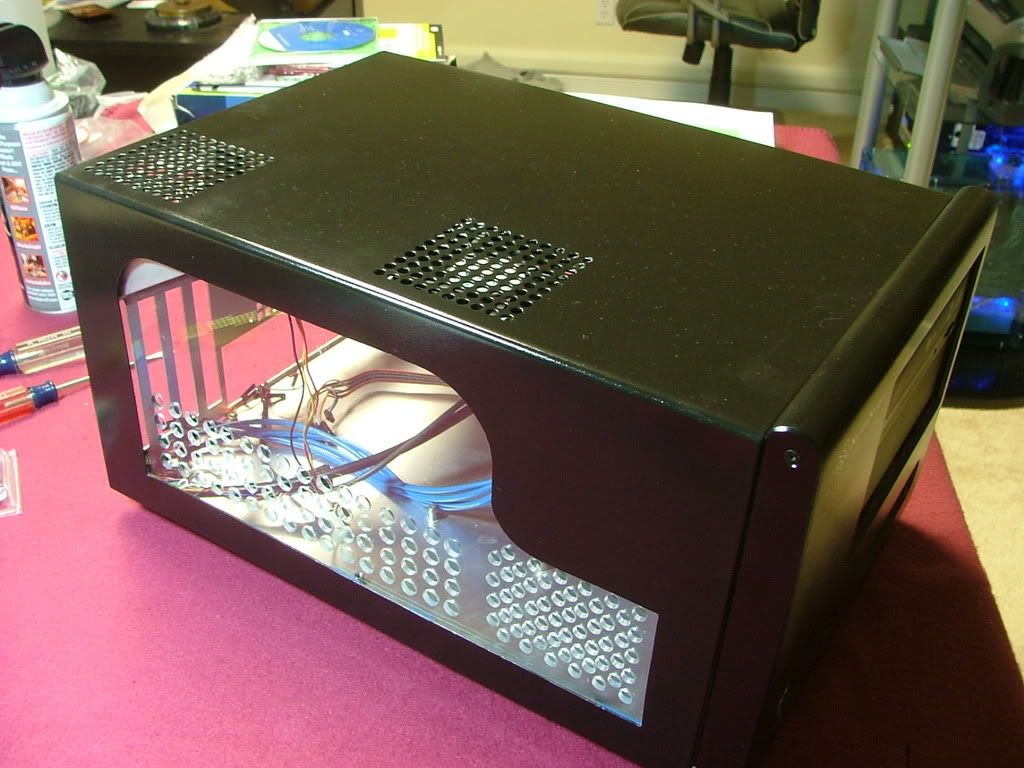
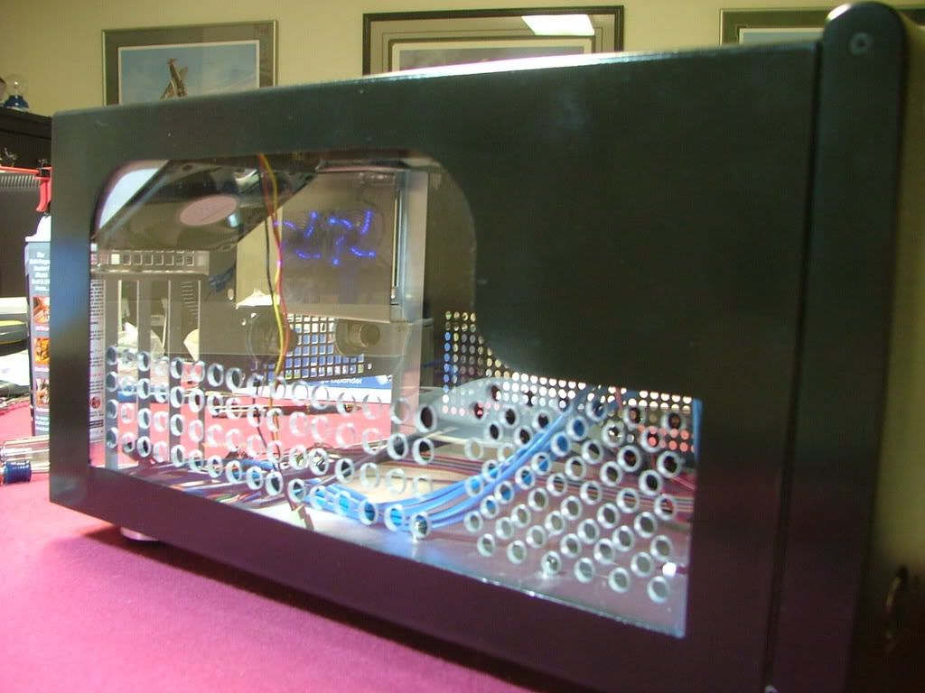
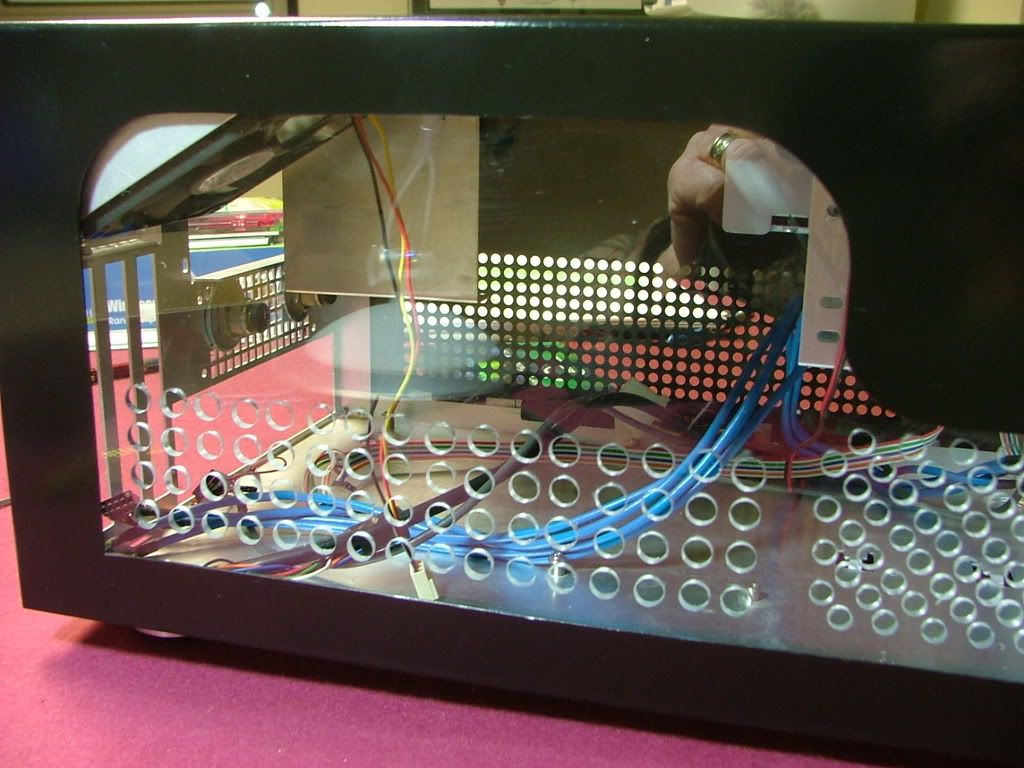
I managed to purchase a piece of Lexan for “drill ability†to use for the window. These pix were while laying out the hole patterns and beginning to drill. While it may appear somewhat inconsistent it was decided on two different size holes and patterns. You may notice the two stray holes up top……that was a “test†in an area not seen. If you look closely you’ll see where the window edge is.
Lexan makes a big difference when it comes to drilling! It was easier by far over the plex but has it own minor issues. Rule of thumb, Plex is hard but brittle where as Lexan is soft and workable. I used a wireless drill at low speeds but it would still grab on occasions. Also I had difficulty in cleaning any “rough†edges and in the process managed to scratch the surface and will need to spend the time to find and use some “glass polishâ€. The major drawback of “softâ€. Here you have it temporarily mounted and in the closer views see some of the needed clean up.
Haven’t been totally “pleased†with it and as stated earlier due to needing additional work have just sat it aside for now. Here is where I can put a plug in for Silverstone’s customer service. They have spare parts for their cases and don’t seem to hesitate to sale them either. While I’m a big fan of Ultra’s MicroFly cases one needs to be “careful†as they will not sale any replacement parts. At any rate I acquired a factory windowed cover until I’m happy with my version.
One of the things I tried to do was to make the WC loop somewhat modular as half of it is outside the case. First with the MicroFly and then with the SG01 I mounted bulkhead fittings so and then an additional set of shutoff valves outside the case. Even though the Aquaduct has its on set of valves I could still stop the flow at the rear of the case. The one thing that I really miss from the Ultra design is the mobo tray which made disassembly very easy. However with the bulkhead fittings mobo removal was all that bad. To cut to the chase and trim the BS I’ll just though out a patch of pics showing this in the past. If there are any specific questions to what is happening just ask.
Also another nice thing about having the loop modular is it allows things like testing and overclocking somewhere other than in the case……….
And then when you're done, in it goes!
0
Comments
Air movement in the SG01 is quit limited if one goes with stock cooling. Admittedly it has lots of cooling holes but fans need to move that and with water cooling fans are in short supply. So after some thought and input am currently doing the following:
1. Made all fans on the left side of the case exhaust with hopes it will cause some kind of air movement through the case (seems to). Adding a fan or fans will be limited by how much (or little) space I have. Also I believe one of the reasons for water cooling was to delete fan noise.
2. Mount a cooling fan for the mosfet passive coolers
On the mosfet part of the deal I rounded up ye old trusty 60 x 35mm that I initially had cooling the NB cooler on the Abit NF-M2 nView / Opty 1210 mobo assembly. I then grabbed the two brackets that were mounting a 120mm fan on the Tech Station.
By mounting the brackets on the “bottom†of the fan I was able to keep it low it in the case so as
1. Not be too close to the PSU
2. Match a couple of holes in the chassis and miss the water cooling bulkhead connectors
3. I’ll think of something later!
In the prior versions it seemed to do the job, with the MSI stock mosfet cooler may have to do a little bit of “flex engineering†to get the mobo to slide under the fan.
An interesting side note when locating the various mobos used so far is that there is not uniformity as to where precisely the mounting holes for the CPU cooler are located. In my referenced picture you see part of the fan resting on one of the thumb screws for the water block. I believe this pic shows the Biostar 760 mobo (#2), but the 780 it replaced didn't have that issue nor the later 790 (all Biostar). So it'll be interesting to see what this MSI will do
I think this will bring DC AM3 up to date and everything afterwards is "as it is happening". :bigggrin:
Several things happened during the migration from DC original to DC v4.0. One of which was where to mount the primary HDD. Originally it was mounted in the case drive cage, but that quickly changed along with the build’s function and then with the elimination of the cage totally because of going with the larger GPUs.
The only place I had was in the top 5.25 bay where I had been hiding the excess PSU cables. It was decided to “borrow†several of the standoffs from BHrDx to mount the unit. However the bay cover also uses the front set of mounting holes so it was off to “hammer, grind, and file to suitâ€. Initially it was necessary to file down the threaded sheet metal on the cover’s mounting legs (here you can see the before….didn’t take an after!). Then on to hand fit the standoffs which took several trips to the vise and file usage before it would “fitâ€.
As it turns out there is about 3/8†under the HDD so I will be trying to hide some of the cable excess there. Please excuse the fuzziness of the first shot of the HDD mounted!
For those that didn’t want to dig back through all the worklogs, here is another “make it fit†mod needed. EBay being my bane, and I managed to get a “good deal†on an Aqua Computer TwinPlex water block.
After waiting with great expectations the chipset block finally came and even though it was the "older" version it is NIB and purrddy!
Only one problem.......... it is for an Intel mobo. For some reason when the seller sent me the pic (post above) it didn't sink in about the intel part. Especially when he said he'd include the other bracket. Now add to the fact it came without mounting hardware.
What’s next are pictures showing the progress of the mod for the NB block. Even though I had the correct mounting bracket, the plex section of the non-intel unit didn’t have the required “relief†to fit correctly. That is why I couldn’t just throw the bracket in place between the copper and the plex. Originally I had thought of drilling or slotting the mounting holes in the acrylic “legs†but didn’t have sufficient material to feel comfortable doing that. The mounting bolts holding the halves together are long enough to allow the bracket to be placed on top.
First I mounted the bracket to see if there are any issues. You can see a gap that also would have not allowed me to use it in the “normal†place. Was hoping this would be all that was required, but when the unit was test fitted on the mobo the mounting “wings†hit components. So the order is, test fit, mark, cut, file/sand (for looks), and finally together.
As I didn’t want to take a chance of braking through the clearance holes I scribed my cut line a bit “off edgeâ€. Also wanting to have more “hand†control the cuts were done with a “hack saw†instead of dremel. Here you have it ready to cut, half way done, and finally awaiting the file.
The sawing was a bit ragged and on one side had a bit more material than originally planned. I used two different files and then finally 1000 grit paper. It wasn’t a total match but give the amount of time I put into the “polishing†(very little) it didn’t turn out too bad!
Here it is as modded, then you have the test installation, and finally with the CPU block. The spacing of the mounting holes on the bracket didn’t allow me to have it “square†to the components but it worked! This has been typical on all the boards used.
One thing that was later pointed out after having been installed and in use was the top block is mounted 90 degrees off. As it seemed to be doing a good job as is I wasn’t about to take everything apart to correct it.
So there you have it and from here on out the worklog is unique to the AM3 only build.
To get things rolling decided to mount the EK water block to the XFX GTX285, which shows my change in bling. Before, I was totally wowed with copper, now it is on to “nickel†for a base color. Zalman can be tagged as the culprit as I’ve always loved their copper coolers, and now the transformation is also because of them. I’m now into the NT series of the CPU coolers which is a “burnish†nickel. On a side note I was originally going to use the BFG 285 OC that was the RMA for the WC’ed 280 but it is Rev2 with the water block rev1. However, was lucky in that the XFX unit was the older PCB layout.
On with the “conversionâ€â€¦â€¦..
Here we have the 285 bare and ready for the big pain as EK provides a 1mil and a 0.5mil “sheet†of thermal tape. Because of the limited amount of material a large number of wee squares were required to be cut and applied. For me the only positive was I shanghaied a friend to do that part!!
Now to apply the TM, try to get everything lined up when sticking them together, and tightening the screws. Unlike other coolers I’ve used there is no fudge factor in mounting using springs or whatever. Care was taken in tightening everything up trying to apply tension evenly and avoid warping the PCB. Here are several pictures of it together, some smaller details, and just shots for S & Gs.
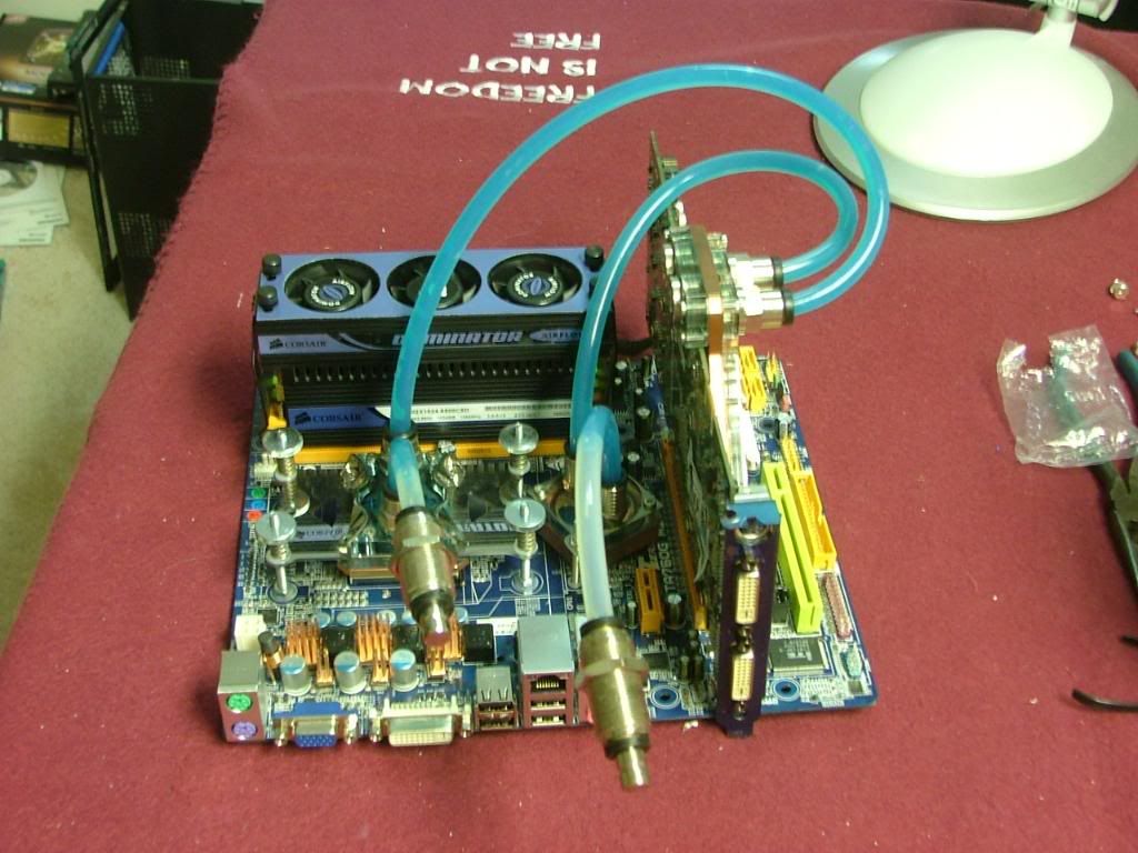
Up next was mounting the water blocks on the 785 and I won’t bore you with the “assembly†part as that hasn’t changed from the prior two times. Mobo, water blocks and gpu at the beginning, the 955BE, and the CPU and nb coolers in place. Finished it off by seeing how the gpu looked.
BTW took this opportunity to correct the orientation of the NB coolers top plate.
From
To
Can you see the difference???
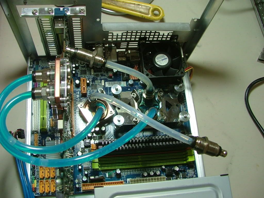
Finally got around to starting the leak testing before cramming it into the SG01. As I had a question about what a leak test really is, I ended up doing what Bubba over at LR suggested.
Before my entire leak testing was done static……I’d run the pump long enough to get most if not all the bubbles out and then turn off the PSU. Why?? Came from the old school of “if you don’t have the power supply hooked up to the mobo when running you will bork it.†However I was reassured that if I had a load on the PSU besides the pump I should be alright. So out of the F/S box I dug out an older 600W unit, plugged in the Aquaduct 240 and a couple of fans and turned it on. 1-1/2 hours later still running and no leaks. Guess a 12 – 14 hour run should be sufficient??
Any way you have the mobo plumbed up getting ready to hookup to the pump/rad/fan assembly, the test starting, a couple of shots of the Ek block (sure is purrddy with the blue coolant), and an overall view of the “test systemâ€.
As mentioned earlier there was a slight issue with the NB and Mosfet cooler that comes with the MSI 785GM-E65…… the two coolers are connected with a heatpipe! It wouldn’t be a biggy except I want to keep the stock Mosfet cooler in place. Again I did some engineering by “Kliensâ€â€¦â€¦snip and tuck!!
Sure hope I don’t have to RMA this board!!
Now on to the system with no name to do some engineering on the fly there.
And then ass_u_me_ing things would fit as before bit me. Remember me mentioning earlier how the mosfet fan clearing the CPU water block was different for each board I dealt with? This time it became an issue……….I’ve gone from the fan sitting on top of a thumb screw to this spacing.
When I started putting the mobo assembly into the case and hooking up the bulkhead connectors a discovery was made. The intake tube to the CPU block was too short! So had to drain the system and replace it.
Also decided to install the memory and mount the memory cooler. Here is where hardware changed a bit. Because of having a death wish I’ve ordered different memory for “the build without a name†so ended up using both 2 x 1GB kits here. Then I go and hid this nice looking G. Skill with a Corsair Dominator cooler.
Because I had to replace the intake tube and shorten the one that goes from the CPU to the GPU it was decided to do a short version of a leak test.
Because of having to change out the tubing the coolant level was low and this brings me to the main thing I do not like about the Aquaduct 240. One needs to remove the whole top plate to fill it.
The leak test has run for about 2 hours now with no leak so going to turn it off and let sit static. Time to crash as I want to get up early to finish fitting the stuff in the case and start painting some parts of no name build.
It has been excellent to see your progress with this though, and I hope this doesn't deter you from bending it to your will - it looks like the effort will be well worth it.
I've had situations like that where everything tests fine on the bench, then put it in where it needs to go and nothing, yet take it back to the bench and it works again. Bloody annoying! Sometimes though, we keep looking for a serious or complicated issue when it can be something simple like a short somewhere or a pin off or a cable backwards. It's not easy to explain to a customer that they spent thousands on proprietary parts replacements because you just realized you had been plugging the special power plug one pin down, blowing the damn thing.
Keep at it and keep us informed, I know you'll lick it!
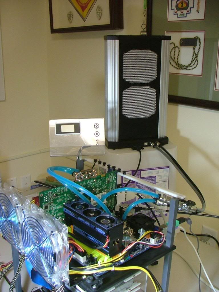
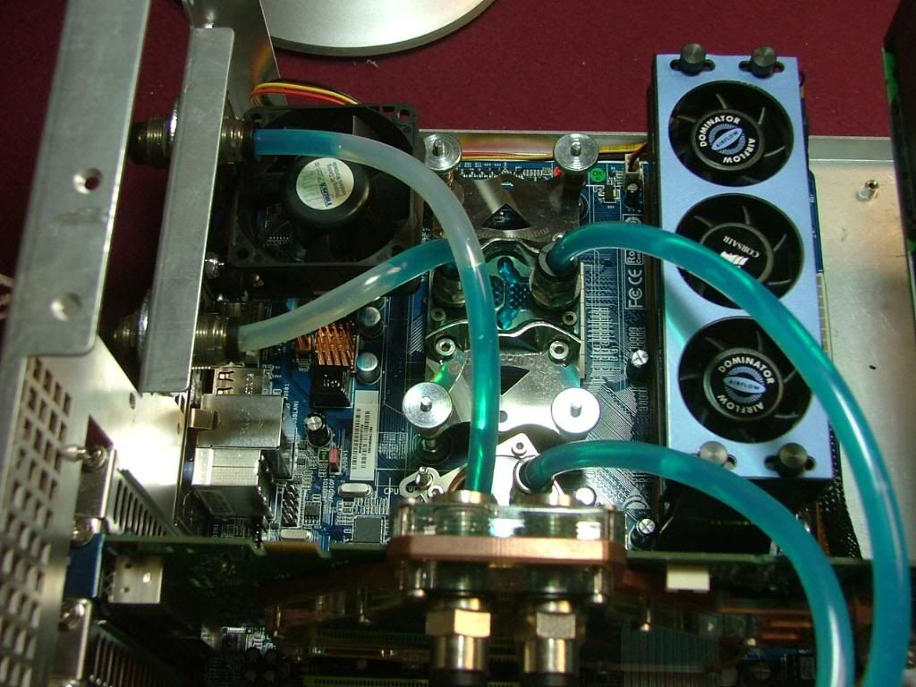
We’ll start with trying to figure out where to hid stuff up to and including some views that show what I consider to be 90%+ completed. Between trying to get rid of bubbles and trying to place cables the ability to disconnect from the Aquaduct sure was a plus. Now I just got to get it to run!!! I can’t handle the “show and no go†mode. As some have asked “why?†- I threw in a picture to show why the tubing is on the left side as I would have had to use at least on 90 degree elbow to miss the PSU hanger.
I gotta make this thing work if for no other reason than to show off that EK water block!!! :rolleyes2
Oh yeah, at some time in this build I need to sleeve them friggen modular cables!!!
Been a slow week!!! Spent the last couple of days trying to re-paint the chassis of the No Name build and look at DC AM3.
did mangae to take it out of the case last night. Didn't notice anything "obvious" on the back side, and then mounted it on the Tech Station. Will be hooking up the PSU and the rest tonight along with honey dos and again working on painting. Here is the system out of the box and then on the test stand. The more I work with the EK waterblock the more I want this case to work so it can be seen!!!
Today around 21:30
Okay long story short........system wouldn't boot up (or at least show video). Unplugged the GPU and tried the on board >> nope! On a wild hair swapped out the PSU and nope....
Standing there with it on scratching my head, then got a wild hair and desided to do something stupid.......I wiggled the NB water block and the scarry part is I now have a working system!
Soooooo put the 285 back in, went back to the original PSU, and loosened the two nuts that hold the NB cooler in place. The system boots up without issue. Right now I can only think of a couple of things 1. the block was literially "too tight" on the chip, or 2. it was not "flat" and may have been touching something on the mobo.
So it looks like I will be putting it back in the box with the hope stuff won't shift the cooler and I can find my friggen notes on my overclock as I can't find anything on the 'puter!
Not sure what the issue was but it must have been related to the NB cooler. I had taken it out as mentioned before and it wouldn’t boot in the Tech Station. For whatever reason something told me to “wiggle†the NB cooler and BAM it booted up! I went in and loosened the nuts holding it in place and did “some adjustments†and it seems to have resolved the situation….your guess is as good as mine.
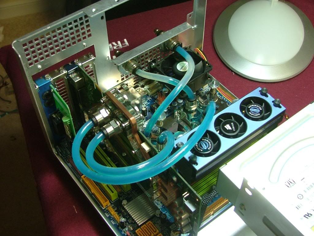
After I had it running on the Tech Station, I mounted the mobo back in the SG01 and hooked up the minimum of stuff & it ran, next up was packing everything back together and powering up, then worked on the wire management. Think it is hit or miss there but “oh wellâ€.
So here it is “where it belongsâ€â€¦â€¦â€¦.
As it now stands I'm trying to do updates and that is when I found the one problem for now. Wanted to have a SATA combo drive in no name so stole the unit out of DC. It was replaced with an IDE unit from the old Kermit case. However for whatever reason it is not powering up or whatever. Also it had been painted green to match Kermit’s interior but now it is an “eye sore†here. So I guess that’ll be an upcoming project when I have the funding to do it.
This ugly M$ Paint “sketch†show about where it would go….what-da-ya think?