
Modding a HighSpeed PC Tech Station
This is thinly veiled excuse to “show off†another of my projects because this is what I’m used to set up, test, and OC all of my mobo assemblies before they go in the box! While I realize this is not a case, it is a mod! Also thought to include this as you'll have references to it in any worklog I bore you with. Again this never "stayed the same" so there is somewhat of a time line again. 
In ’06 I got lucky over at vhforums and won myself a Standard "Top Deck" Tech Station from HighSpeedPC. Wasn’t too enthused with the idea of the motherboard on the bottom so when I saw a how to change this at virtual-hideout, the mod was on!! BTW when I won it there was no "Top Deck" destincsion. It seems that AC Ryan goodies and this arrived.
After all the parts were in had to figure out what needed to be done. Referring to the stock instructions and the mod guide I kinda sorta knew what I wanted to do, maybe. Because of needing to mount the HDD side plates, one more item was added to the Lowes shopping list mention in the vhforums article. Lowes #880729, Pan Head M3 x 16mm bolts.
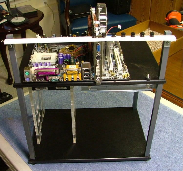
The first thing I did was make the top the bottom.
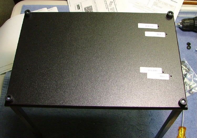
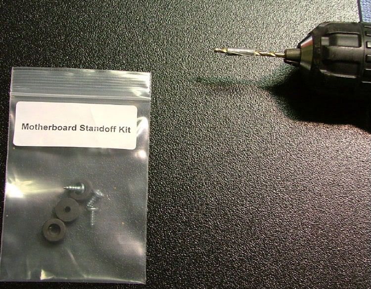
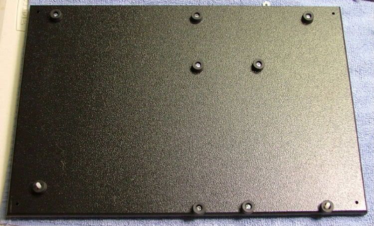
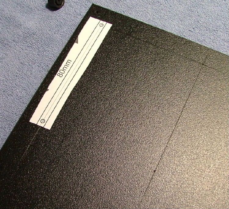
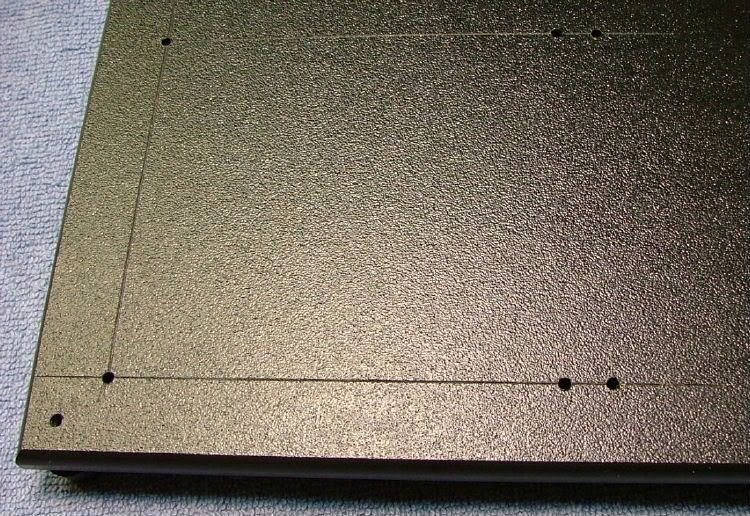
Then mounted the mobo standoffs on what is now top plate using the pre-drilled holes. At this time I added the “optional†mATX standoffs. Caution, there is an error in the online instructions (it may have been corrected as I notified them) that states to use a 7/16†drill for the pilot holes USE A 7/64†DRILL! In the pic you’ll notice my ¼†dept gage for the drill – retro but it works (gotta love duct tape!!). And then all in place.
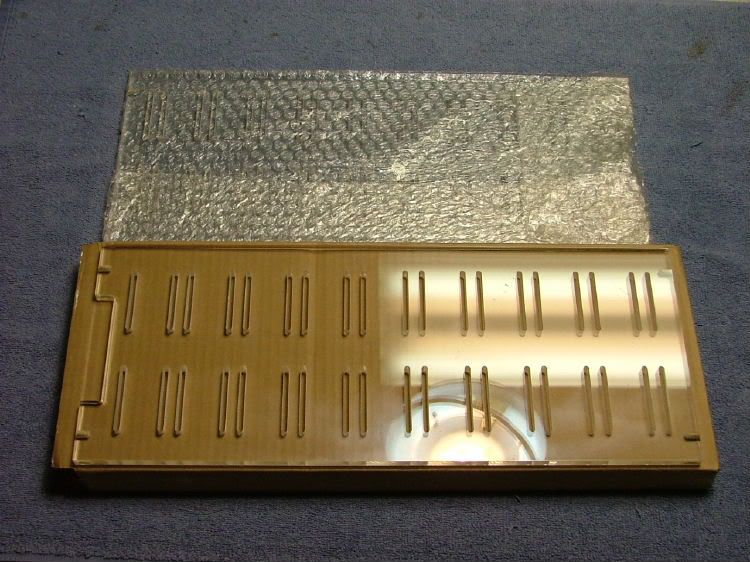
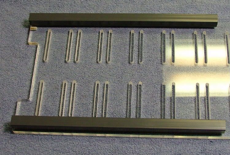
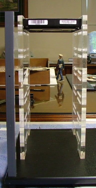
Next on the list was to shorten the acrylic drive plate/panels to match the 10†legs. So why not just use the legs as a guide!
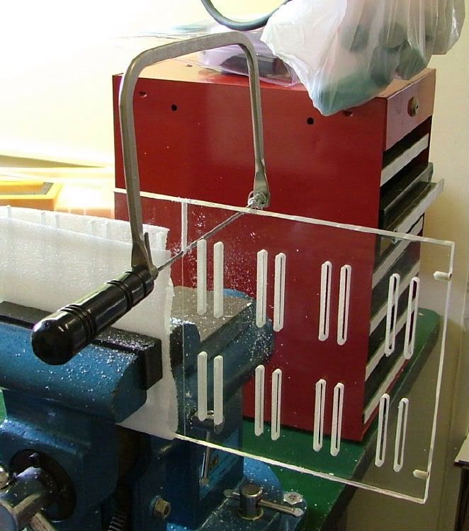
So into the vise they went and here you see getting ready to start, starting, and then turned over to finish the cut. The cuts weren’t the best but I sanded for “flatness†and then said screw it as the cut wouldn’t be seen.

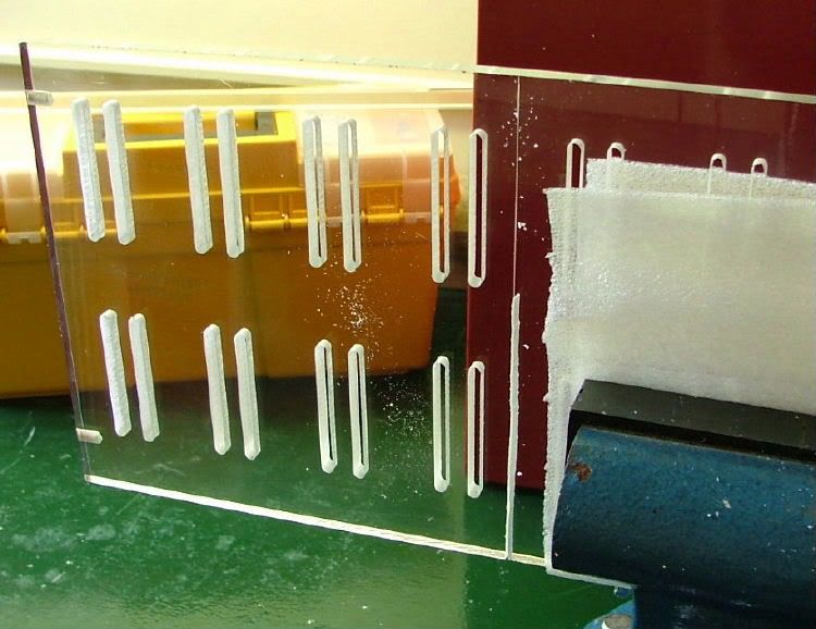
Using a couple of “spare†half height HDD’s to hold the sides together, it was time to figure out where to put the HDD cage and allow space for a PSU.
Alrighty then, know where I want it - so time to locate the holes. Easy,
just use the down loaded guide!
WRONG!! Don’t know what I did, but when I printed it out it wasn’t to scale!! Re-located two holes (glad these will be hidden!!) and mounted the unit.
When it came time to mount the optical drive, I had planned on doing it the same way as in the “how to†article. Unfortunately for me during that time frame I had several cranial infarctions! So there are no pictures that I am willing to release on that!!
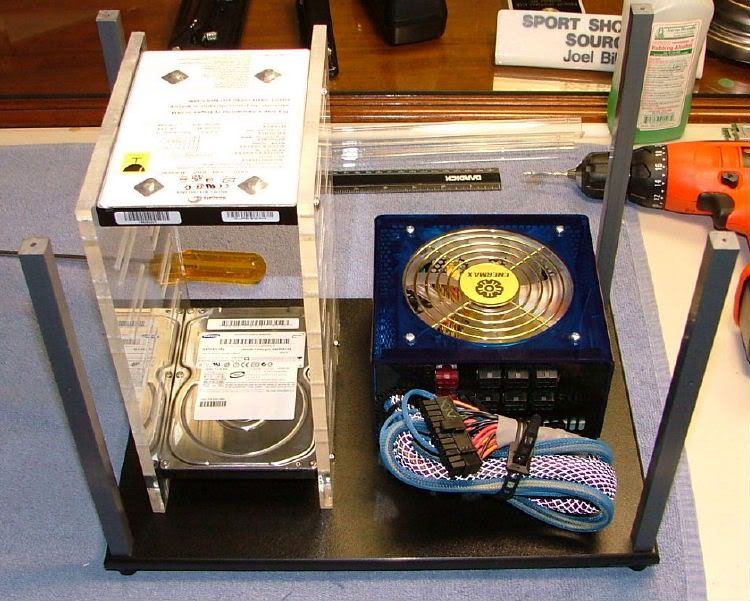
The two short legs for the pci-mounting bracket (covered in reference article) were shortened. At this time I hadn’t decided the where and how of mounting the fan that came with the kit. There is very little room on top because an ATX board fills the top shelf. A consideration had been given to mounting the fan somehow to cool the HDDs as one was to be a Raptor.
I call this the front, where HighSpeedPC calls it the rear
So in theory the mod was complete except for mounting the fans, so here
is what it looked like and where HighSpeedPC refers to this view as the front >> to me it is the rear!
Here is a straight on view of the rear
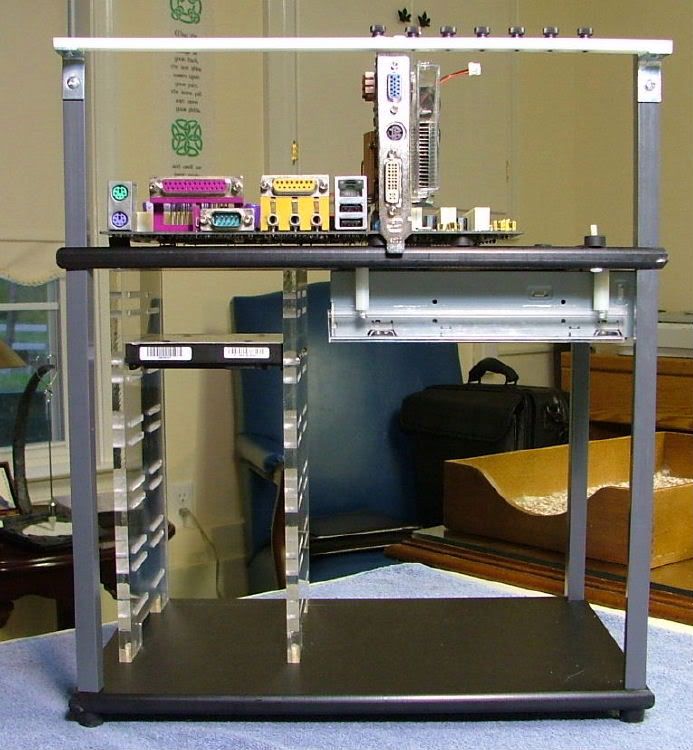
And I’ll finish it off with a view of both sides
Then it was time to figure the how and where to mount the fan Also got a wild hair about possibility of mounting two blue leds at the base of both acrylic side plates. Also needed to consider how the PSU will be mounted, either cut the supplied non-skid material for the bottom shelf or maybe screw mount the PSU to keep it from moving. Heck, haven’t even finalized what PSU is going to be used yet!!
To get this far took me approximately 6 - 7 hours where as an organized person could have done it in 3 - 5 and been neater!
In ’06 I got lucky over at vhforums and won myself a Standard "Top Deck" Tech Station from HighSpeedPC. Wasn’t too enthused with the idea of the motherboard on the bottom so when I saw a how to change this at virtual-hideout, the mod was on!! BTW when I won it there was no "Top Deck" destincsion. It seems that AC Ryan goodies and this arrived.
After all the parts were in had to figure out what needed to be done. Referring to the stock instructions and the mod guide I kinda sorta knew what I wanted to do, maybe. Because of needing to mount the HDD side plates, one more item was added to the Lowes shopping list mention in the vhforums article. Lowes #880729, Pan Head M3 x 16mm bolts.
The first thing I did was make the top the bottom.
Then mounted the mobo standoffs on what is now top plate using the pre-drilled holes. At this time I added the “optional†mATX standoffs. Caution, there is an error in the online instructions (it may have been corrected as I notified them) that states to use a 7/16†drill for the pilot holes USE A 7/64†DRILL! In the pic you’ll notice my ¼†dept gage for the drill – retro but it works (gotta love duct tape!!). And then all in place.
Next on the list was to shorten the acrylic drive plate/panels to match the 10†legs. So why not just use the legs as a guide!
So into the vise they went and here you see getting ready to start, starting, and then turned over to finish the cut. The cuts weren’t the best but I sanded for “flatness†and then said screw it as the cut wouldn’t be seen.
Using a couple of “spare†half height HDD’s to hold the sides together, it was time to figure out where to put the HDD cage and allow space for a PSU.
Alrighty then, know where I want it - so time to locate the holes. Easy,
just use the down loaded guide!
WRONG!! Don’t know what I did, but when I printed it out it wasn’t to scale!! Re-located two holes (glad these will be hidden!!) and mounted the unit.
When it came time to mount the optical drive, I had planned on doing it the same way as in the “how to†article. Unfortunately for me during that time frame I had several cranial infarctions! So there are no pictures that I am willing to release on that!!
The two short legs for the pci-mounting bracket (covered in reference article) were shortened. At this time I hadn’t decided the where and how of mounting the fan that came with the kit. There is very little room on top because an ATX board fills the top shelf. A consideration had been given to mounting the fan somehow to cool the HDDs as one was to be a Raptor.
I call this the front, where HighSpeedPC calls it the rear
So in theory the mod was complete except for mounting the fans, so here
is what it looked like and where HighSpeedPC refers to this view as the front >> to me it is the rear!
Here is a straight on view of the rear
And I’ll finish it off with a view of both sides
Then it was time to figure the how and where to mount the fan Also got a wild hair about possibility of mounting two blue leds at the base of both acrylic side plates. Also needed to consider how the PSU will be mounted, either cut the supplied non-skid material for the bottom shelf or maybe screw mount the PSU to keep it from moving. Heck, haven’t even finalized what PSU is going to be used yet!!
To get this far took me approximately 6 - 7 hours where as an organized person could have done it in 3 - 5 and been neater!
0
Comments
Early May, 2006
Never leaving anything alone, I had already begun to make changes! One was a necessity, which was to add three more mobo pad/standoffs
Why? A “third†size in mobo!! Look to the right and you’ll see that the edge of the mobo is too narrow to rest on the “stock†size mobo pads.
As mentioned earlier this station was to be a temporary home for Celtic Spirit’s (again on indefinate hold) hardware. The 3 HDD’s were taken care of but not the original Digital Doc 5+, 52X CD-R, and CD-RW/DVD-RW. The plan had been to make sure every thing ran before boxing it up!
And because of this the original mounting rails for the optical drive (refer back to the multiple views and you’ll see the original designed location) weren’t going to work, so what to do? Ahhh yes, the tops of the A.C. Ryan side plates used for the HDD’s! They needed to be shortened to allow room for the PSU to go underneath. Here are a couple of pics showing first fitting
Since a minivan’s worth of stuff was crammed into a sub-compact the fit is tight to say the least. HDD’s would have to be in-place first, then the optical needed to have all the cabling done first before sliding all the way in.
While it is apart I tried to figure how to mount the fan for the HDD area. The problem; attach it under the top made it too high, but if mounted on the bottom shelf it’s too low! Then again the only real “hot†HDD would be the Raptor, so if I mount it below the FDD (archaic aren’t I) I could go the high road. Or then again mount all of the HDD’s in the lower three spots and hope the SATA cables are long enough.
Have to say though HighSpeedPC defiantly has a nice product here and look forward to seeing what their next version will be like!
Sometime Earlier in 2007
As usual was only able to work on it sparingly and did a lot of “designing on the fly†to get to this point.
Kinda sorta “solved†the location of the 3.5 drives cooling by using the provided 120mm fan and two of the 1†standoffs that came with the station. For aesthetics, I lined up the outside edge of the fan with the outside edge of the station “legâ€. This also allowed space for any cables that may be in the area. Also to give it more of a finished look I painted the provided 1†angles black. As a matter of fact I also painted the two 1†brackets used to mount the PCI “tie down barâ€.
To provide extra cooling on the topside for the mobo components, two more 120mm fans were added. Originally more 1†brackets were acquired for this duty, however while laying out the how & where of mounting the 2 fans that idea was dropped. It seems because of designing “on the fly†based on the mod done to the large tech station I keep forgetting I do not have the same amount of room!
To somewhat “improve†the issue, 2†brackets are used instead. First the “leg†that is mounted to the fan was shortened and then these were also painted black. It was decided earlier to mount them on the top of the platform to give a little “elevation†to the fans. Because these brackets come with two mounting holes per leg I consider them as being “adjustableâ€!
The two fans were mounted for mockup purposes but for S & Gs I thought about using LED fans for “blingâ€. The “on the fly engineering†caught up with me as I drilled the mounting holes using the 1†bracket. It turned out the larger ones used are wider, and add to the equation of having to locate the brackets against a couple of the rubber mobo standoffs some binding and offset occurred.
March - April, 2007
Again because of the “others†a limited amount of the “fabrication†work went on during the other two builds, but a couple of “ah s**ts†stopped everything ‘till I could pay more attention.
While working with the optical drives in the 5.25 bay area it was apparent that my spacing had error in the minus direction. So I re-drilled the clearance holes and still had to “wobble†the holes to make them slotted.
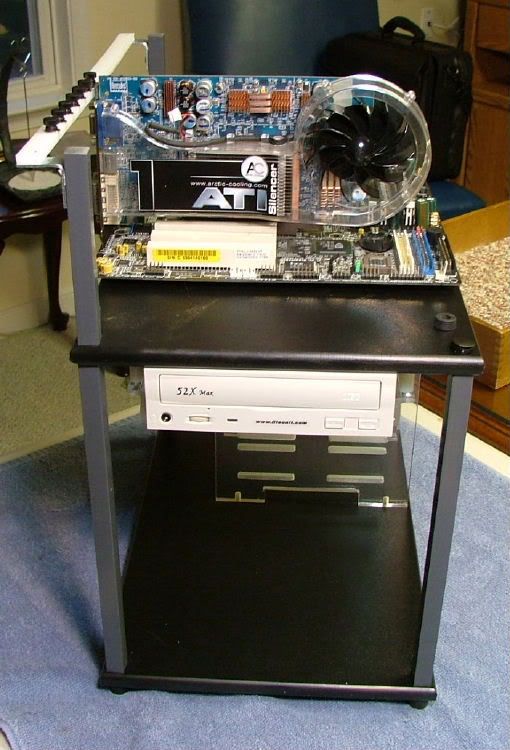
It seems I could mount a 5.25 item in the two lower areas without issue, but would have to loosen the cage mounting screws to get anything to fit in the top area. Also will have to order a “newer†generation of CD/DVD-Rom as the one I was going to use is close to 8†deep. This puts the rear very close to the 3.25 drive cage. Here is one of my earlier mockup shots showing this:
Now what does a picture frame have to do with the build? Had another one of my “wild hair†“design on the fly†ideas. HighSpeedPC provides a “kit†with speaker, power, reset, HDD led, and power LED they are individual units on 3†– 4†leads. Having these mounted directly to the mobo just didn’t appeal. One of my earlier builds has a neat little PCB with all of stuff hard wired, and after a lengthy search I found one. Also I picked up a small dual lead LCD temp gage for the station (remember this thing started when all I was using was Skt. A). Then I searched for a cheap, quick, and “dirty†way to mount these. Enters the frame. You know, one of those cheap ones where you slide the picture in.
When I finally got around to doing the cutting and drilling found out it was not the best of choices. The plastic is fragile and you get all of the cracks, splits, and things. Was too far into doing this when this really showed itself, so finished it as is and maybe down the pike look for an alternative.
Borrowing one of the left over nylon spacers, several washers, and a screw made a “swivel base†so as to be able to access the buttons and view the temp gage from several directions as needed.
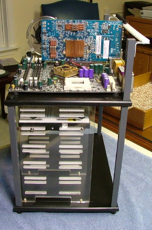
Got my LED fans in and mounted, painted the fan grills “anodized†blue, and started trying to figure how I wanted to mount stuff. Started with the 3.25 cage and supposedly it’s three “fixed†items – fan controller, FDD, and HDD. Until I really start “hooking things up†a mobo the FDD and HDD are in flux. Trying to figure how I would route the communication cables and more than likely go “retro†and use ribbon cables (optical drives, etc. too). Here you have “Frontâ€, “Sideâ€, & “Rear†views as it now stands.
Last Changes in '07
Adding to the Swiss cheese effect that is starting to be the trademark of build is this new design.
Besides the power control PCB I ditched the wee little provided speaker for one similar to BluHaz reDux v2.0's, a nice healthy 2†in diameter. Had originally planned for it to be in the frame, but dropped the idea after concerns of more holes and a way to mount it. Not having that much room on the “deck†it gets mounted under the mobo. One should still be able to hear it with the mobo on its standoffs.
Wanted to see what it would look like lit up so I tied into BH rDx’s PSU and this is what we have…….first shot is with the fans on “low†(dims the leds also) and then on “highâ€. Then I tossed in a look at the 3.25 cage to show the rear fan and a “detail†of the fan controller. BTW added that because it was floating around and most likely will never really be required to run the fans full bore.
February 2008
The PSU ended up being an old Enermax EG475AX-VE SFMA 470W I had sitting around. The Tech Station comes with a rubber mat that one is supposed sit items on and let their weight hold them in place. This PSU will not let me do that – time for a history lesson. This unit was the second one I had customized by performance-pcs for Celtic Spirit. Had the cables “modularized†(this is before manufacturers started doing it) and sleeved. As this was going in a full server style box tight bend rads on the cables weren’t an issue. So to make the mobo related cable look different I had them done in the “Reflex Stainless Steel†sleeving. Now that stuff is hard to bend so that alone determined how I have to mount the PSU.
For those of you who have the windshield mounted “Fast Pass†– “Multi-Pass†– “EZ Pass†for toll roads will recognize these
The interlocking tabs a courser and stiffer than Velcro and lock together real well, and the mounting adhesive seems to be fairly strong also. As this particular unit is “square†I used two (will add two more later) and located on the bottom of station. The reason for adding the second pair is so I can rotate the PSU 270 based on how much cable is needed to reach the mobo.
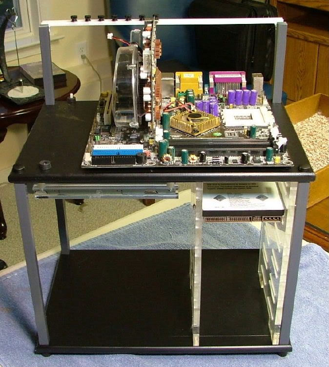
Currently using this to test and OC DreamCatcher v2.0’s mobo assembly so wanted to show it “in useâ€. One thing for sure cable management isn’t!
The power cable mentioned above can be seen in number 2 & 3. With this arrangement had a problem with the power led…… the harness on the Station is pin-pin-blank and the abit is pin-blank-pin. However with the 3 led fans and illuminated fan controller don’t think there will be a problem figuring out we have power!
Below are a couple of shots with the unit fired up the first time (had boot issues so it was back to the drawing board mobo wise). First thing was to turn down the fan speed as it sounded like a small tornado, other than that everything Station seemed to be working.
Originally tried to find a way for me to test both ATI and nvidia GPUs with the same HDD. Did figure it out and didn't want to buy two copies of M$ Windows so I could run two separate HDDs or a partitioned drive. So eventuallu I ignored it! No really, decided to just set up a "new" HDD (the Raptor from Celtic Spirit) that will be used with the Abit / Brisbane combo I'll be currently testing.
Now testing and over clocking, so.......
Nope, don’t need no fargging Power LED!!
Now this thing is "up to date"......... except I did steal the 120mm fan that was to cool the HDDs for another build!
Whats up with all the IDE and floppies?
I'm an old fart stuck in the past??
In the tech station just too lazy to pull it and just haven't spung for a cd/dvd reader that is sata!! As of right now only one system has an FDD and that is because it is also a 7 in 1 card reader.
Oh think we've all been there one or twice!! :bigggrin:
Sometimes I shoot too much for bling then functionality.
It's ugly, but running. there is a q6600@3.2 in there and load temps are in the mid 40's.
That flat area has come in handy. It will hold my monitor and kb/mouse (and coffee)
Top is 15 1/2"x 24"
The most important item!!!!!