Electric Home Brewery, Electrical Assistance Request
 MAGIC
Doot DootFurniture City, Michigan Icrontian
I am not an electrical engineer or a certified electrician so I'm looking for some input. I have a good knowledge of AC and DC but aside from doing general home wiring repairs and PC wiring I don't have a lot of experience.
The project I am working on now is an electric home brewery. This isn't a new concept, and there are a lot of people that have built very similar setups. I didn't want to fallow a guide/plan and not really know what I was doing, so I did a lot of reading on electrical circuits and components to determine what I need based on what I'm trying to do. Here's a description of what I'm trying to do.
- 62qt stainless steel kettle heated by a 5500w heating element.
- The heating element will be controlled by a Solid State Relay and PID controller .
- 1/20hp pump for recirculating liquid in the kettle and draining.
- LED indicator push button switches for Main Power, Heating Element, and Pump
- Pump is also on on a Rheostat to control flow.
In summary, the element should be drawing 23A (5500w/240v), pump (37.29/115v)
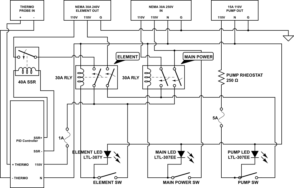
Primary Goal: don't die. Secondary, build this as safely and efficiently as possible. This is the diagram I came up with.
I'm looking for some feedback, suggestions, improvements, confirmation that I did this correctly or not. Thanks!
The project I am working on now is an electric home brewery. This isn't a new concept, and there are a lot of people that have built very similar setups. I didn't want to fallow a guide/plan and not really know what I was doing, so I did a lot of reading on electrical circuits and components to determine what I need based on what I'm trying to do. Here's a description of what I'm trying to do.
- 62qt stainless steel kettle heated by a 5500w heating element.
- The heating element will be controlled by a Solid State Relay and PID controller .
- 1/20hp pump for recirculating liquid in the kettle and draining.
- LED indicator push button switches for Main Power, Heating Element, and Pump
- Pump is also on on a Rheostat to control flow.
In summary, the element should be drawing 23A (5500w/240v), pump (37.29/115v)

Primary Goal: don't die. Secondary, build this as safely and efficiently as possible. This is the diagram I came up with.
I'm looking for some feedback, suggestions, improvements, confirmation that I did this correctly or not. Thanks!
3


Comments
And, my primary question is should I go with a 40A contactor relay for the Main Power switch? I wasn't sure if the 27A total was too close to the 30A max on that main contactor.
I don't have any AC power experience to add, but it looks reasonable to me. Also make sure you get AC relays.
Got started today mounting all the components in the chassis.
A shot of the front, the PID controller, Red (main power), Yellow (Heating Element), Blue (pump), the lower red device is a flashing/buzzing alarm for a boil temp indicator, a rocker switch to turn off the alarm, and the other hole is for the pump rheostat.
I'll get started wiring it up this week.
A stainless steel threaded probe, like this.
Also, this is really freaking sweet. Once this has proven itself, I think I just might have to build a one.