This is part of a multi-chapter series detailing my first attempt at a custom liquid cooling setup. Previous entries can be found here and here.
At last, after getting back into overclocking and testing a variety of air and liquid coolers, it is time to move fully into the realm of liquid cooling with my first-ever custom build. Believe me, there’s no asterisk in that statement either—what you’re seeing is my actual first build and notes on what went right as well as what went wrong. Hopefully nothing catastrophic happens (although I did manage to break my hand in a totally unrelated incident), but if it does you can be sure I’ll provide the gory details.
I’m definitely nervous about this part of the project; after all, computers don’t traditionally play well with liquids, yet here I am putting the two in close proximity to each other.
As stated in the previous chapter, there were problems with overclocking the AMD system, so it was traded out for the Intel benchmarking system which overclocks from its stock 3.4GHz to 4.8GHz quite nicely.
The parts
CPU block: XSPC Raystorm
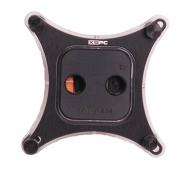
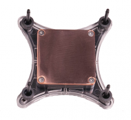 Originally the XSPC Rasa was going to be used, but thanks to a hardware change and neglecting to read compatibility information, I ended up purchasing a second CPU block. A bit of research showed the Raystorm outperformed the Rasa, so it gets to stick around.
The XSPC Raystorm has a very highly polished copper base. On the opposite side are the liquid channels which use 1/4 inch threaded holes for barbs or compression fittings. Its clear plastic retention collar simply sits around the block which could make installing a bit of a pain as there are many parts to hold together when installing the block. There are four small holes around the collar to allow the included blue LED kit to be easily installed. An aluminum plate sits on top of everything and provides a nice mask to the lighting.
For those wondering, the block comes with mounting hardware for Intel sockets LGA 775, 1155, 1156, 1366, and 2011. It does not appear to be compatible with AMD sockets.
Radiator: Koolance Triple 140mm Copper High Flow Radiator (HX-CU1403V)
 This radiator is pretty excessive right now; only the CPU is being cooled by the loop. The thing is, this radiator was chosen with future upgrades in mind. Ok, that and it was the biggest thing that would fit in the case.
This Koolance radiator holds up to three 140mm fans, and has a fin density of 30 fins per inch. It uses 30mm screws to hold itself in place, allowing for fans to be placed between the radiator and case.
Pump: Danger Den / Laing DDC Rev. 3.25
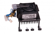 This pump was recommended to me a while back by a couple of experienced forum members, which is why I chose it.
Interesting fact: there is only one moving part in this pump. This is supposed to extend the pump’s life, reduce its energy consumption, and improve its performance over its predecessor.
Another interesting fact: this pump uses 3/8″ leads for liquid, not 1/2″ as described on the store page. This left me with the option of using a pair of 3/8″ to 1/2″ adapters for the pump or a replacement of the tubing and barbs. Since I didn’t want to deal with the potential for liquid pressure or volume issues that could come along with moving to a larger tubing size, I went with the replacement barbs and tubing.
Reservoir: Aquacomputer Aquabox Professional 5.25″ Bay Reservoir
 Originally I had selected the Phobya Dual 5.25″ bay reservoir. Unfortunately I missed two siginificant details about this part. First, there is no groove half way up the reservoir, and therefore its path is blocked by two drive support rails between the bays. Second, there is only one screw hole per side at the back of the reservoir. The drive bay clips use two pins to hold devices in place. I didn’t feel like breaking out any tools and cutting the case, so it was time to replace yet another part.
The Aquacomputer Aquabox reservoir was chosen partly because it fits in one bay, and partly because the built-in window provides a cool visual when liquid is flowing. It doesn’t hold nearly as much as the Phobya reservoir—it occupies about half the depth of a single 5.25″ bay—but it should hold enough coolant for now. While the Aquabox’s capacity isn’t listed on the manufacturer’s website (or any of the sites that sell it), it appears to hold about 120ml (about 4oz) of fluid.
Coolant: Distilled water
The loop will use distilled water for the coolant for now. It’s the most common and certainly the cheapest cooling material available at under a dollar for a gallon. Tap water is not advisable due to the minerals, bacteria, and other substances it contains. These things would quickly build up in the loop and cause major problems. Distilled water lacks these substances and can be used safely.
Other bits and pieces
 There are some other miscellaneous parts as well, such as the tubing, barbs to hold the tubing in place, and an external power supply for filling the loop and bleeding the air from the system.
The GPU will remain air cooled for now, but this will likely change in the future.
The install
For a “first time” project, I’d say it went well. That isn’t to say it was a hassle-free experience, but overall it was smoother than what I expected.
First of all, the radiator needed to be flushed. A new radiator can have small bits of metal or other debris in it that could damage the lines, so it’s best to remove those things. Several rounds of hot water, shaking, and draining took care of that.
The next step was to remove the top fan shroud, front face, and both sides of the case. No problem. With that accomplished, the top panel became the first build issue. Some of the screws holding the Switch 810‘s top panel to the rest of the case were extremely tight…to the point where I broke one screwdriver bit and bent another trying to remove the panel. I’m not sure whether the screws were over-tightened or what, but several of them just didn’t want to move.
The radiator was a bit of a pain to install because the screws holding it to the top panel had to also go through all three fans. Due to the shape of the top panel (there is a large ridge around the sides of this panel), fans couldn’t just be slid into place as needed—all three fans had to be lined up correctly and sandwiched between the radiator and top panel. The slightest bump, and everything would go out of alignment. Of course, with a little patience and a lot of tiny adjustments things went into place. Reinstalling the top panel was quite simple, even with the additional height of the radiator.
The CPU block installed just like any air cooler: find the appropriate back plate for your socket of choice, and mount the block to that plate. My only concern here was with a lack of feedback on how tight the screws should be. There is a spring underneath each screw which is supposed to help maintain tension on the block, but the directions weren’t clear on how much tension there should be aside from stating the tension should be even on all the screws. The only real difficulty came from the plastic collar that sits on the CPU block: it’s a separate piece, so there are actually three major pieces to keep in place when mounting (back plate, water block, and collar). The included blue LEDs fit pretty snugly in holes on the collar’s side and provide a nice effect for showing off the loop.
I purchased a heatsink kit for the pump that came with some long mounting screws, which made the pump’s installation quite straightforward. The pump was installed in the fan grille just above the I/O panel. To be honest, I’m not quite sure where the pump would have gone had this not been the case—there wasn’t a suitable spot anywhere else in the Switch 810. It’s a convenient spot especially since this puts all liquid parts in a fairly direct line with each other.
The reservoir installed just like any optical drive—a couple of screws and it’s secured in a drive bay. The only negative here is the 1/4″ hex wrench required to open the fill ports was not supplied.
The barbs simply screw into place. Tubing was a simple matter of measurement and routing. The tubing is held to the barbs by metal collars left over from a homebrewing project. For maintenance, I’ve included a drain system, which is comprised of a T-connector, a length of tubing, and an end cap attached to the pump output. The drain will be in-line just after the pump’s output to make coolant removal as easy as possible. When not needed, it can be tucked safely away in an out-of-sight location.
Filling the loop and bleeding the air out requires a bit of attention to a bunch of things all at once. As it turns out this is a skill I am not good at. I was watching the water move through the line while ignoring the reservoir—don’t make this mistake. Fortunately the reservoir was in the front of the case with very few components below. The SSD, fans, and small areas of the case were easy to finish drying with a box fan. I’m pretty sure a power supply would have been more difficult.
Bleeding the air out of the line took a bit of time, patience, refilling (being careful not to repeat the spilling incident), and careful tipping of the case. Oh, and an external power supply with a molex connector to power the pump independently of the system. This also serves as a pretty good leak test. Once the large air pockets were removed (there were still some tiny bubbles that flow with the water), I let the pump run for a couple hours to make sure nothing was going to spring a leak.
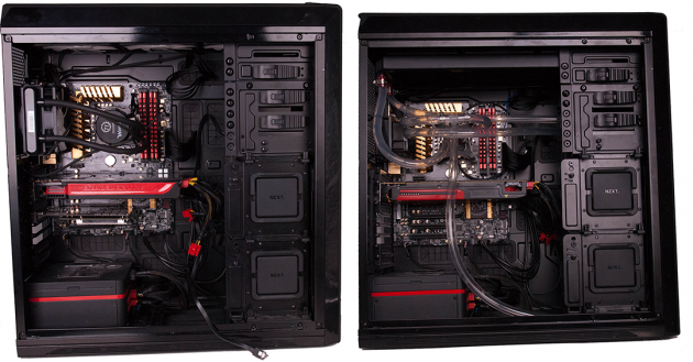
This left one remaining thing: finish reassembling the case. This went well until it was time to put the window panel back on. As it turns out, there was a flaw in my assumptions about the tube routing—it wasn’t quite flexible enough to make the extra bend required to properly attach the window panel. I have some 90 degree elbows on the way, but they won’t get installed until the water gets changed out for the next review.
The test
Finally, it was time to bring the system fully online and begin testing. As with the previous chapter, the room was set to 70F and the CPU started at its stock 3.4GHz and gradually raised until the system was no longer stable—the CPU limit remains a respectable 4.8GHz. Turbo mode was disabled, and (unlike the ‘extreme’ record-setting overclockers) all four cores remain enabled during testing. Hyperthreading was enabled. AIDA64’s stability test was used to keep all four cores at 100% load. CoreTemp was used to capture temperature data.
Again, due to some limitations in the tube’s ability to bend, this set of tests is with the left side panel removed. I do not believe it affects the results, but it is possible there could be slight differences.
So how does the custom loop compare to the previous cooling solutions?
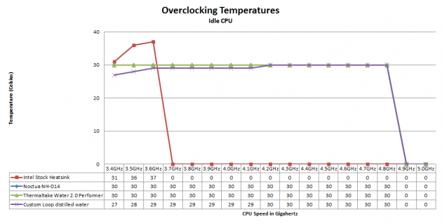
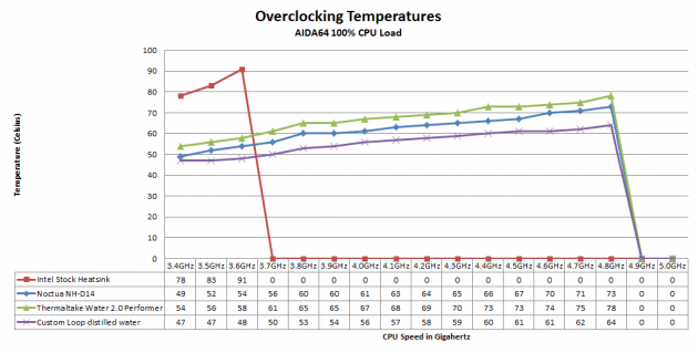
And there you have it. My first real liquid cooling build, and I’d say it’s mission accomplished. While there isn’t much difference between the three non-stock coolers at idle, load temperatures are a completely different story. At full load, the custom loop starts out just slightly cooler than the Noctua, and does nothing but improve from there. In fact, the higher our CPU’s clock speed, the better the custom loop performs, eventually achieving a nine degree advantage over the top air cooler, and a fourteen degree advantage over the Thermaltake cooler.
There is another important factor to consider, and that is the cost of the custom loop. The Thermaltake Water 2.0 Performer costs $84.99 on Newegg before rebates, while the Noctua air cooler currently sells for $83.99. Of course, both of these excellent coolers can often be found on sale—sometimes far below their normal prices. The cost of the custom build (before shipping) is detailed below.
- Pump: $114.75
- Reservoir: $54.95
- CPU Block: $62.99
- Radiator: $85.89
- Barbs: $45.00
- Tubing: $13.50
- Drain parts: $9.50
- Collars: $8.00
- Coolant: $0.99
- Total (before shipping): $395.57
It’s pretty safe to say that costs go up significantly to achieve these improvements. There are ways to reduce the cost—smaller radiator, pump/reservoir combo, etc—but in the end it will end up being more expensive than air or a self-contained system. The important thing is to either set a budget and stick to it, or set a performance goal and save up.
Wrapping it up for now
Now that the build is completed, let’s take a look at how it stacks up to my original goals. Does the custom loop outperform the Noctua NH-D14? Absolutely. Did I fry the computer? Nope, the system survived in spite of my best efforts. Does it look better? Well, that’s arguable at the moment because the case won’t close because the lines weren’t quite flexible enough, but this will be fixed before the final chapter of this series. I think once the elbow joints are installed, things will improve significantly.
This leaves one final chapter for the series: the Ice Dragon Cooling’s coolant review. It’s the thing that got this whole project started, and soon we’ll see just how it performs.






 Articles RSS